Configuration procedure
Before starting the configuration, obtain the
microScan 3 Core - PROFINET GSDML
file and the software tool
Safety Designer®
from SICK's website first. Make sure
both the file and the software tool are in the latest versions.
Detailed procedures about how to configure the laser scanner are detailed in
SICK
microScan3 Siemens PLC integration instruction manual - TIA Portal
and
SICK
microScan3 Siemens PLC integration instruction manual - SIMATIC Step 7
.
Following described roughly:
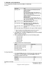
1 Connect the laser scanner to the PLC and controller.
See the physical connection in
Connecting the laser scanner(s) on page 79
2 Open configuration software tool
Safety Designer®
.
3 Set IP address and PROFINET name in
Configuration
>
Addressing
.
•
The scanner IP address must be in the same network segment with
the PLC and controller, that is, 192.168.10.XXX.
•
The PROFINET name must be the same in the PLC configuration.
4 Set
F-destination address
to
12
in
PROFINET
area in
Configuration
>
Protocol Settings
.
5 Define the two protection fields in
Configuration
>
Fields
.
6 Define the source for input signals of the scanner and configure basic settings
for the inputs and outputs in
Configuration
>
Inputs and outputs
.
The
Use one input source
checkbox must be selected and choose
Rx:
Process image (6 Bytes)
from the drop-down list.
7 Create monitoring cases and assign the fields that are to be monitored to
each monitoring cases in
Configuration
>
Monitoring cases
.
Configuring the PLC
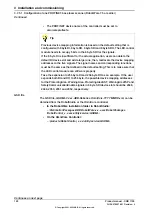
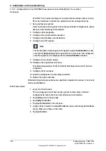
The safety PLC connecting to the laser scanner and controller must support
PROFIsafe and can act as a master. Before configuration, make sure the PLC is
loaded with the GSD files of the controller and laser scanner.
Detailed procedures about how to add an external device to the PLC and how to
configure detailed settings, see the user manual from the vendor. Following lists
the necessary settings during PLC configuration:
•
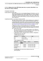
Add the scanner to the PLC by adding a
mS3 6Byte In/Out PROFIsafe V2.6.1
module.
The parameters f_dest_address and f_source_address are set to 12 and 1,
respectively.
•
Add the controller to the PLC by adding the
DI 8 bytes
,
DO 8 bytes
,
SDI 8
bytes
and
SDO 8 bytes
modules.
The parameters f_dest_address and f_source_address for the SDI are set to
3 and 2, respectively, and for the SDO are set to 5 and 4, respectively.
•
Make sure the address for the SDO signal is the first address of
SDO 8 bytes
slot.
Continues on next page
Product manual - CRB 1100
127
3HAC078007-001 Revision: J
© Copyright 2021-2023 ABB. All rights reserved.
3 Installation and commissioning
3.7.5.2 Configuration of one PROFIsafe-based laser scanner (RobotWare 7.6 or later and PLC acting
as Master)
Continued
Summary of Contents for CRB 1100
Page 1: ...ROBOTICS Product manual CRB 1100 ...
Page 162: ...This page is intentionally left blank ...
Page 184: ...This page is intentionally left blank ...
Page 652: ...This page is intentionally left blank ...
Page 698: ...This page is intentionally left blank ...
Page 712: ...This page is intentionally left blank ...
Page 714: ...This page is intentionally left blank ...
Page 719: ......


