4-131
Note:
The time deviation in PWM mode is ±12.5%. If pulse PWM is outside of the deviation range the pulse input
is not active.
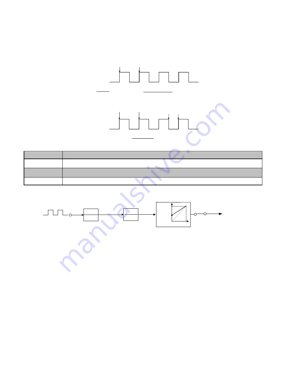
Diagram for pulse input selection:
03-30 = 0
(Normal Mode)
Sample
Pulse train
T
△
Period
1
T(Period)
F=
03-30 = 1
(PWM Mode)
Pulse Frequency
(03-27)
Pulse command=
Frequency
x 100%(01-02)
T(Period)
Pulse Input Command=
T1(Period)
x 100%(01-02)
Sample
Pulse train
T
△
Period
T1
△
Period
03-33
Pulse Input Bias
Range
【
-100.0~100.0
】
%
03-34
Filter Time of Pulse Input
Range
【
0.00~2.00
】
Sec
* Refer to section 3.7 table 2 control terminals for details.
* Refer to figure 4.3.27 for the pulse input specification.
1+ST
1
K
1
03-28
03-33
0%
10%
Filter
Gain and Bias
00-05 = 4
Frequency
reference
K
△
Pulse input
frequency(03-27)
T
△
Pulse input
filter time (03-34)
Pulse
train
Figure 4.3.27 Pulse input adjustment
Setup Pulse Input as Frequency Reference
Set parameter 00-05 to 4 and 03-30 to 0 to use the pulse input terminal PI as the frequency reference source.
Refer to Figure 4.3.5. for details. Next set the pulse input scaling (03-27), enter the pulse input frequency to match
the maximum output frequency. Adjust the pulse input filter time (03-34) in case interference or noise is
encountered.


