


SIEPYEUOQ2A01G AC Drive Q2A Technical Manual
769
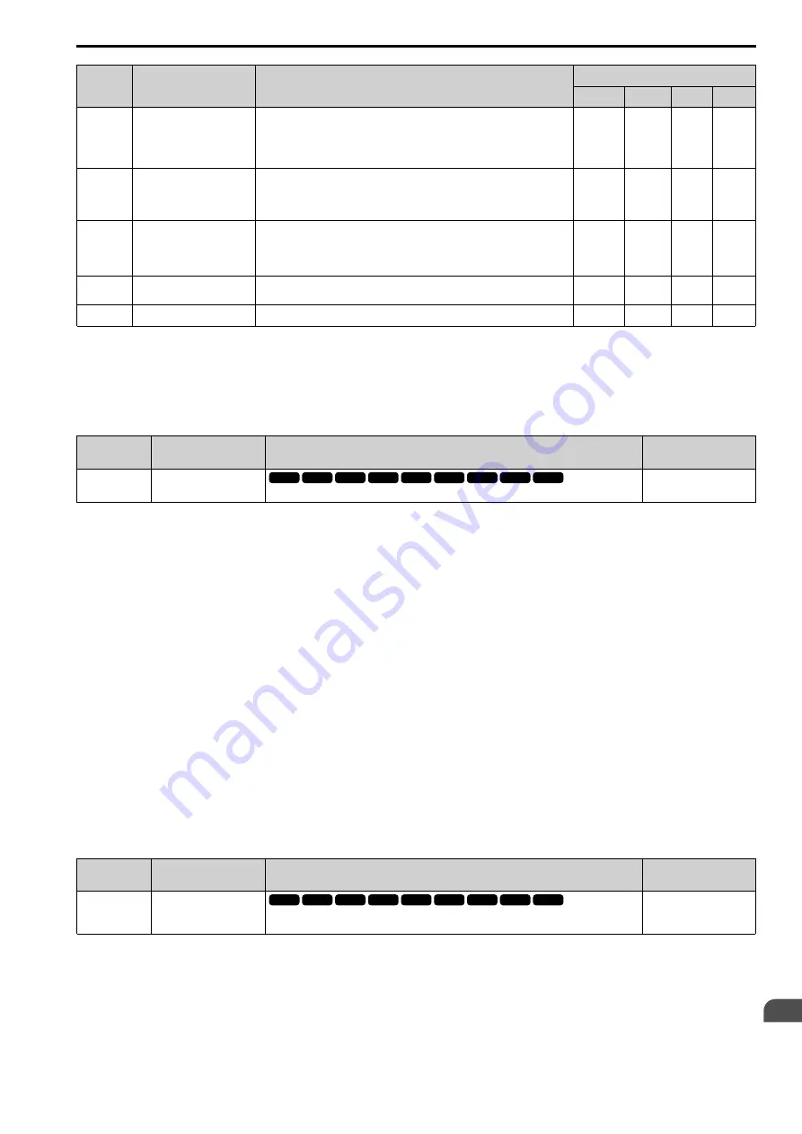
No.
Name
Setting Method
L2-29 [KEB Method]
1
2
3
4
L2-11
KEB DC Volt Setpoint
•
Single Drive KEB Ride-Thru 2
Set to approximately 1.22 x input voltage.
•
Single Drive KEB Ride-Thru 1, System KEB Ride-Thru 1, or System KEB
Ride-Thru 2
Set to approximately 1.4 x input voltage.
x
x
x
x
L3-20
DCBus VoltAdj Gain
•
If
ov
or
Uv1
occur at the start of deceleration when you use KEB operation,
increase this value in 0.1 unit increments.
•
If there is torque ripple during deceleration when you use KEB Ride-Thru,
decrease the value.
-
x
-
-
L3-21
OVSup Acc/Dec Gain
If there is large speed or current ripple, decrease the value in 0.05 unit increments.
Note:
If the setting value is too low, then the drive will have unsatisfactory DC bus
voltage control response. The drive can detect
ov
or
Uv1
.
-
x
-
-
L3-24
Acc@Rated Torque
Set the motor acceleration time to the maximum frequency at the motor rated
torque.
-
x
-
-
L3-25
Load Inertia Ratio
Sets the ratio between motor inertia and machine inertia.
-
x
-
-
*1
When
L2-29 = 1 [KEB Method = Single KEB1 Ride-Thru]
, the drive will automatically set
C1-09 [Fast Stop Time]
in KEB Tuning.
If you must not change the Fast Stop time, do not do KEB Tuning.
*2
If you do KEB Tuning when
L2-29 = 2, 3, or 4 [KEB Method = Single KEB2 Ride-Thru, System KEB1 Ride-Thru, or System KEB2
Ride-Thru]
, the drive will automatically set
L2-06 [KEB Decel Time]
.
*3
The drive sets this value automatically when KEB Tuning completes correctly.
■
L2-01 RideThru@PwrLoss
No.
(Hex.)
Name
Description
Default
(Range)
L2-01
(0485)
RideThru@PwrLoss
Sets the drive operation after a momentary power loss.
0
(0, 1)
The drive detects momentary power loss when the drive DC bus voltage is less than the value set in
L2-05 [UV
Detection Lvl (Uv1)]
.
0 : Disabled
1 : Enabled
The mode is defined using
L2-50 [RidThruMode@PwrLoss]
.
Note:
When you set
L2-01 and L2-50
, make sure that you know these items:
•
You can use a Momentary Power Loss Unit on models 2004 to 2056 and 4002 to 4031 for a longer momentary power loss ride through
time. A Momentary Power Loss Unit makes it possible to continue operation of the drive after a maximum of 2 seconds of power loss.
•
When you set
L2-01 = 1 and L2-50 = 0 to 3
, keep the magnetic contactor between the motor and the drive closed and keep the control
signal while the drive does KEB operation.
•
When you set
L2-01 = 1 and L2-50 = 1 to 4
,
Uv [Undervoltage]
will flash on the keypad while the drive tries to recover from a
momentary power loss. The drive will not output a fault signal at this time.
•
When you use a magnetic contactor between the motor and the drive, keep the magnetic contactor closed while the drive does KEB
operation or tries to restart with Speed Search.
•
Keep the Run command active during KEB operation. The drive cannot accelerate back to the frequency reference when the power
returns.
•
When you set
L2-01 = 1 and L2-50 = 2 to 4
, if the control power supply voltage is less than the CPU operation level during KEB Ride-
Thru, it will trigger
Uv1
.
■
L2-02 RideThrough Time@Power Loss
No.
(Hex.)
Name
Description
Default
(Range)
L2-02
(0486)
RideThrough Time@Power
Loss
Sets the maximum time that the drive will wait until trying to restart after power loss.
Determined by o2-04 and
C6-01
(0.0 - 25.5 s)
This function is applicable when
L2-01 = 1 [RideThru@PwrLoss = Enabled] and L2-50 = 0, 2
[RidThruMode@PwrLoss = Timer Controlled, KEB Mode]
. If power loss operation is longer than the time set in
this parameter, the drive will detect
Uv1 [DC Bus Undervoltage]
, turn OFF output, and the motor will coast to
stop.
Note:
•
The length of time that the drive can recover after a power loss changes when drive capacity changes.
•
The upper limit of the possible momentary power loss Ride-Thru time changes when drive capacity changes.
V/f
CL-V/f
OLV
CLV
AOLV
OLV/PM
OLV/PM AOLV/PM CLV/PM
EZOLV
V/f
CL-V/f
OLV
CLV
AOLV
OLV/PM
OLV/PM AOLV/PM CLV/PM
EZOLV
Содержание Q2A
Страница 2: ...This Page Intentionally Blank 2 SIEPYEUOQ2A01G AC Drive Q2A Technical Manual...
Страница 12: ...12 SIEPYEUOQ2A01G AC Drive Q2A Technical Manual...
Страница 18: ...i 2 Legal Information 18 SIEPYEUOQ2A01G AC Drive Q2A Technical Manual...
Страница 28: ...1 2 Features and Advantages of Control Methods 28 SIEPYEUOQ2A01G AC Drive Q2A Technical Manual...
Страница 64: ...2 9 Installation Methods 64 SIEPYEUOQ2A01G AC Drive Q2A Technical Manual...
Страница 166: ...4 9 Test Run Checklist 166 SIEPYEUOQ2A01G AC Drive Q2A Technical Manual...
Страница 172: ...5 2 European Standards 172 SIEPYEUOQ2A01G AC Drive Q2A Technical Manual...
Страница 173: ...Standards Compliance 5 5 2 European Standards SIEPYEUOQ2A01G AC Drive Q2A Technical Manual 173...
Страница 174: ...5 2 European Standards 174 SIEPYEUOQ2A01G AC Drive Q2A Technical Manual...
Страница 175: ...Standards Compliance 5 5 2 European Standards SIEPYEUOQ2A01G AC Drive Q2A Technical Manual 175...
Страница 176: ...5 2 European Standards 176 SIEPYEUOQ2A01G AC Drive Q2A Technical Manual...
Страница 258: ...6 2 Modbus Communications 258 SIEPYEUOQ2A01G AC Drive Q2A Technical Manual...
Страница 356: ...8 7 Storage Guidelines 356 SIEPYEUOQ2A01G AC Drive Q2A Technical Manual...
Страница 357: ...SIEPYEUOQ2A01G AC Drive Q2A Technical Manual 357 9 Disposal 9 1 Safety Precautions 358 9 2 Disposal Instructions 359...
Страница 360: ...9 2 Disposal Instructions 360 SIEPYEUOQ2A01G AC Drive Q2A Technical Manual...
Страница 526: ...11 20 Parameters Changed by PM Motor Code Selection 526 SIEPYEUOQ2A01G AC Drive Q2A Technical Manual...


