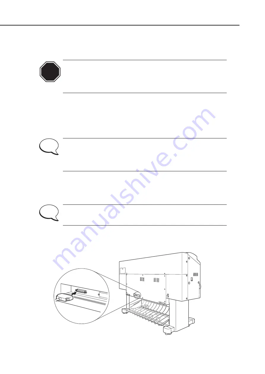
2.1.14 Connecting the interface cable
Use the SCSI interface cable to connect the printer to a computer or to an optional
hardware RIP.
• Avoid connecting other SCSI devices between the printer and the
computer, or print failure may occur.
• When the printer is connected to a computer or a hardware RIP, be sure
to power on the printer first and then power on the RIP, and finally
power on the computer.
Follow the instructions below to connect the interface cable.
1) Make sure that both the printer and the computer are turned off.
2) Attach the SCSI cable to the printer's SCSI connector.
3) Attach the other end of the SCSI cable to the computer or the hardware RIP.
• The interface on the printer is Fast SCSI (SCSI-2) compatible. The length
of the SCSI cable must not exceed 3 m. The connector on the printer is a
D-sub half pitch 50-pin (female).
• The printer has built-in SCSI termination. It is impossible to disable the
termination.
4) Turn the printer on.
5) Enter the User mode
(
.
6) From the "Parameter settings" menu, select "SCSI ID."
7) Specify the SCSI ID number for the printer.
Select the SCSI ID from the numbers 0 to 7 so as not to conflict with that
of the SCSI interface board mounted on the computer. The ID of the SCSI
board on this printer is typically configured as number 6.
Part 3: Operations
BJ-W9000
3-22
CAUTION
Figure 3-22 Connecting the Interface Cable
NOTE
NOTE
Содержание BJ-W9000
Страница 2: ...0201 GR 0 35 0 ...
Страница 3: ......
Страница 20: ...This page is intentionaly left blank ...
Страница 131: ...3 81 BJ W9000 Part 3 Operations This page intentionally left blank ...
Страница 143: ...4 5 BJ W9000 Part 4 Technical Reference This page intentionally left blank ...
Страница 199: ...4 61 Part 4 Technical Reference BJ W9000 This page intentionally left blank ...
Страница 251: ...5 31 BJ W9000 Part 5 Maintenance This page intentionally left blank ...
Страница 358: ...9 CIRCUIT DIAGRAM Refer to the Parts Catalog for the part layouts on each board Part 5 Maintenance BJ W9000 5 138 ...
Страница 359: ...5 139 BJ W9000 Part 5 Maintenance This page intentionally left blank ...
Страница 420: ...SERVICE MANUAL ...
Страница 440: ...Page 4 1 1 OPERATION OVERVIEW OVER Part 4 OPERATION VIEW ...
Страница 452: ...Page A 1 1 CIRCUIT DIAGRAM A 2 2 LOCATION OF ELECTRICAL COMPONENT ON THE PCB Part 6 APPENDIX ...
Страница 455: ...This document is printed on 100 recycled paper PRINTED IN JAPAN IMPRIME AU JAPON CANON INC ...


