background image


Performing Routine Maintenance

Replacing the Electron Multiplier

Thermo Scientific

TSQ 9000 Hardware Manual

83

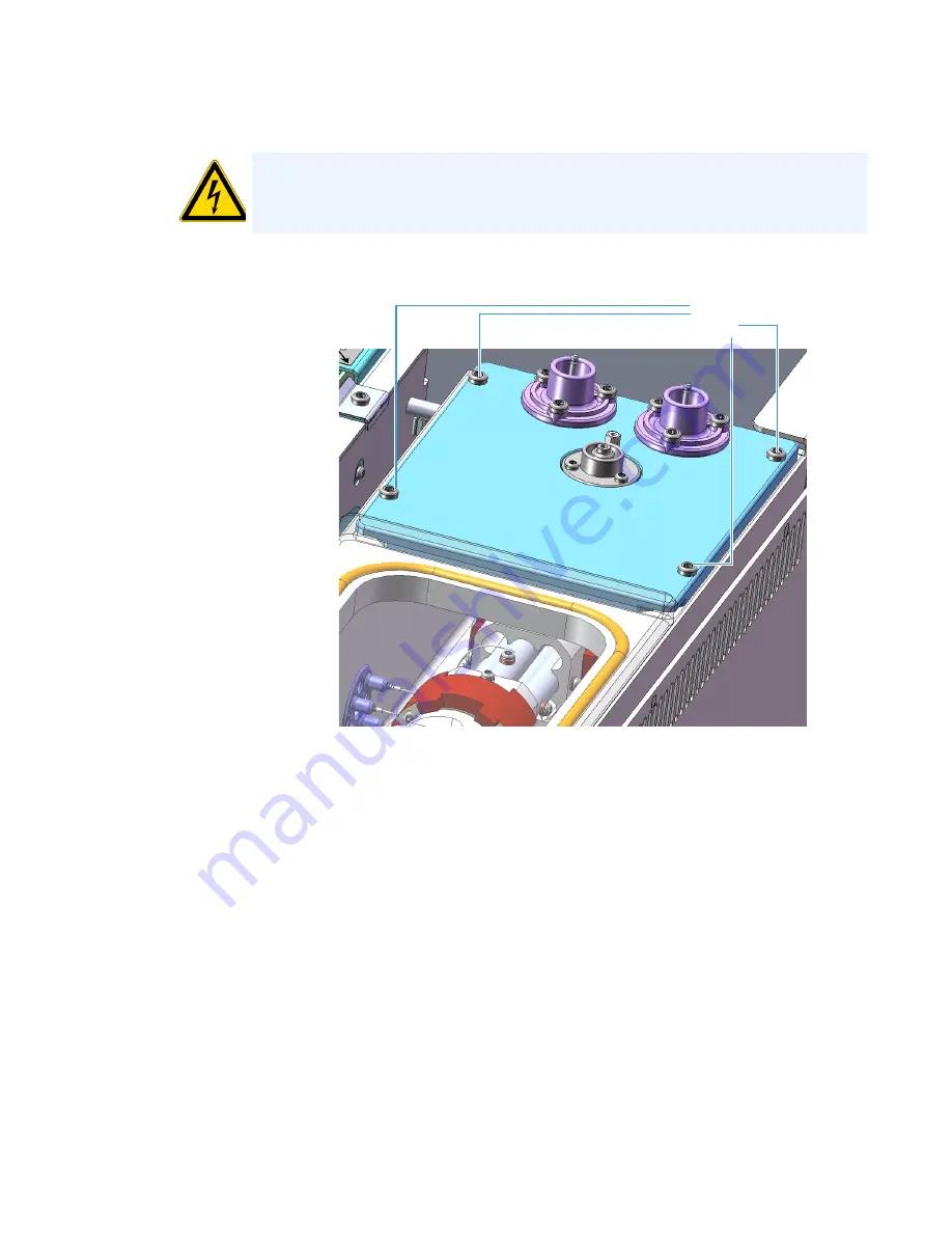
13. Lift the electron multiplier plate out of the vacuum manifold.

AVERTISSEMENT RISQUE D’ÉLECTROCUTION

évitez de faire tomber les vis entre le châssis 

et le couvercle latéral ou la carte. Si vous déposez une vis, trouvez-la avant de remettre 
l'instrument sous tension.

Figure 74. 

Disconnecting the Electron Multiplier Plate

Electron 
Multiplier Plate 
Screws

Summary of Contents for TSQ 9000

Page 1: ...TSQ 9000 Mass Spectrometer Hardware Manual 1R120618 0003 Revision C December 2018 ...

Page 2: ...the whole or any part of this document is strictly prohibited except with the written authorization of Thermo Fisher Scientific Inc The contents of this document are subject to change without notice All technical information in this document is for reference purposes only System configurations and specifications in this document supersede all previous information received by the purchaser Thermo F...

Page 3: ...zard Warning Note xxvi Venting Toxic Gases xxvii Contacting Us xxvii Chapter 1 Performing Routine Maintenance 1 Maintenance Supplies and Tools 3 Configuring the TSQ 9000 System 4 Powering On the TSQ 9000 System 7 Powering Off the TSQ 9000 System 10 Replacing a Column 12 Replacing a column in a TSQ 9000 system with no VPI or an AEI ion source 12 Replacing a column on a TSQ 9000 system with a VPI an...

Page 4: ...ample data are not acquired 106 GC is not communicating with the PC 106 Autosampler is not communicating with the PC 106 Investigating Contamination Issues 107 Chemical noise is at m z 429 355 281 108 Chemical noise is at m z 207 429 355 281 108 Chemical noise is at m z 149 167 279 108 Chemical noise is at m z 43 57 71 85 99 etc 108 Spectra is showing solvent contamination 108 Investigating Filame...

Page 5: ...nment is unstable 120 Signal response is unstable or shows unexpected drop out 120 Investigating Tuning Issues 121 Tune is interrupted 122 Cannot find calibration gas peaks 122 Cannot perform detector gain calibration 122 Cannot calibrate resolution 122 Cannot perform mass calibration 122 An air leak has been detected 122 TSQ 9000 Tune reports an error while saving a Tune file 123 Contacting Techn...

Page 6: ...Q 9000 System 228 Reassembling the Advanced EI Ion Source Cartridge 231 Replacing Components of the Source Exchange Tool 234 Replacing Components of the Vacuum Interlock 238 Replacing Components of the Manifold 252 Manifold Door Hinge 253 Front Manifold Plate 259 Back Manifold Plate 269 Magnet Yoke Manifold O Ring and Source Retainer Magnets 272 Vent Valve Knob and O Ring 274 Replacing Components ...

Page 7: ...es 357 Power Module 358 Dynode and Multiplier Power Supply 362 Replacing the Calibration Gas Components 367 Calibration Gas Module 368 Calibrant Reservoir Kit 376 Transfer Line 378 Replacing the Collision Gas Components 382 Replacing Fans and Filters 390 Front Wire Mesh Filter 392 Left Rear Wire Mesh Filter 393 Chassis Cooling Fan and Fan Plenum 394 Air Deflector 400 Turbo Cooling Fan and Turbo Co...

Page 8: ......

Page 9: ...d safety standards as described in the next section or sections by product name Changes that you make to your system may void compliance with one or more of these EMC and safety standards Changes to your system include replacing a part or adding components options or peripherals not specifically authorized and qualified by Thermo Fisher Scientific To ensure continued compliance with EMC and safety...

Page 10: ... this instrument in a manner not specified by Thermo Fisher Scientific could impair any protection provided by the instrument THIS DEVICE COMPLIES WITH PART 15 OF THE FCC RULES OPERATION IS SUBJECT TO THE FOLLOWING TWO CONDITIONS 1 THIS DEVICE MAY NOT CAUSE HARMFUL INTERFERENCE AND 2 THIS DEVICE MUST ACCEPT ANY INTERFERENCE RECEIVED INCLUDING INTERFERENCE THAT MAY CAUSE UNDESIRED OPERATION CAUTION...

Page 11: ...ce This product is required to comply with the European Union s Waste Electrical Electronic Equipment WEEE Directive 2002 96 EC It is marked with the following symbol Thermo Fisher Scientific has contracted with one or more recycling or disposal companies in each European Union EU Member State and these companies should dispose of or recycle this product See www thermoscientific com rohsweee for f...

Page 12: ...diese RoHS Anweisung fallen finden sie unter www thermoscientific com rohsweee Conformité DEEE Ce produit doit être conforme à la directive européenne 2002 96 EC des Déchets d Equipements Electriques et Electroniques DEEE Il est marqué par le symbole suivant Thermo Fisher Scientific s est associé avec une ou plusieurs compagnies de recyclage dans chaque état membre de l union européenne et ce prod...

Page 13: ...on technique Complex mixtures of individual compounds can be injected into the GC either manually or by an autosampler and then separated for presentation to the MS The MS will generate a mass spectrum of the GC eluate and its components The mass spectrum can then be used for qualitative identification as well as accurate and precise quantification of the individual compounds present in the sample...

Page 14: ...manufacturer the protections provided by the equipment might be impaired If you maintain a system outside the specifications listed in this guide failures of many types including personal injury or death might occur The repair of instrument failures caused by operation in a manner not specified by the manufacturer is specifically excluded from the standard warranty and service contract coverage AV...

Page 15: ... Windows 10 Operating System 64 bit English only or Windows 7 Professional Operating System 64 bit Microsoft NET Framework 4 0 or later Thermo Scientific Xcalibur and Foundation softwarea Thermo Scientific TraceFinder softwareb Thermo Scientific Dionex Chromeleon softwareb a Check release notes for compatibility with TSQ Series instrument control software b Check release notes for compatibility wi...

Page 16: ...ace that could or might cause burn injuries ELECTRICAL SHOCK HAZARD Indicates that an electrical shock could or might occur FIRE HAZARD Indicates a risk of fire or flammability could or might occur FLAMMABLE GAS HAZARD Alerts you to gases that are compressed liquefied or dissolved under pressure and can ignite on contact with an ignition source This symbol indicates this risk could or might cause ...

Page 17: ... your instrument s documentation to ensure your safety and the instrument s operational ability Failing to carefully read the documentation could or might put you at risk for a physical injury TOXIC SUBSTANCES HAZARD Indicates that exposure to a toxic substance could occur and that exposure could or might cause personal injury or death For the prevention of personal injury this general warning sym...

Page 18: ...u une blessure physique peuvent ou pourraient survenir DOMMAGES À L INSTRUMENT indique que l instrument ou le composant pourrait subir des dommages Ces dommages pourraient ne pas être couverts pas la garantie standard RISQUE SOULÈVEMENT indique qu une blessure physique peut ou pourrait survenir si un objet n est pas soulevé par deux personnes ou plus RISQUE MATÉRIEL ET YEUX indique que des dommage...

Page 19: ...essures personnelles ce symbole général d avertissement précède le mot AVERTISSEMENT et est conforme à la norme ISO 3864 2 Dans le vocabulaire des signes ANSI Z535 ce symbole indique un risque de blessures personnelles si l instrument est utilisé de manière inappropriée ou en cas d actions dangereuses Ce symbole et un autre symbole de sécurité approprié vous avertissent d un risque imminent ou pot...

Page 20: ...ection You should post No Smoking and No Open Flames signs to identify hydrogen sources and cylinders Maintain inspect and leak test all hydrogen sources regularly All hydrogen shutoff valves should be clearly marked and permanent hydrogen piping should be labeled as such at the supply or discharge point and at regular intervals along its length Where hydrogen gas piping passes through a wall the ...

Page 21: ... and contraction The system should also include considerations for the most severe condition of temperature and pressure expected during service Piping and supports must be able to withstand static loading introduced by such things as ice and snow and dynamic loading from high wind and earthquake Caution should be used if burying hydrogen piping Proper controls should be used to protect against da...

Page 22: ...tory space that has a piped gas supply system If necessary the piping system should have uninterruptible pressure relief The pressure relief system should be designed to provide a discharge rate sufficient to avoid further pressure increase and should vent to a safe location outside or to a ventilation system exhaust Purchasing Hydrogen Use the following guidelines when purchasing hydrogen Hydroge...

Page 23: ...his precaution applies when the hydrogen is or is not in use Indoor storage of spare hydrogen cylinders has special requirements which is beyond the scope of this document Documentation for each vessel should include a description of the vessel a list of available drawings or other documents the most recent inspection results and the responsible person s name Prevent spare cylinders from toppling ...

Page 24: ...ectric power lines close to other flammable gases liquids or close to public areas It should be readily accessible to authorized personnel and delivery equipment but protected from physical damage or tampering As liquid hydrogen systems also have a cryogenic hazard additional safety considerations for the use of cryogenic liquids might be necessary ...

Page 25: ...A Code Of Practice CP33 The Bulk Storage of Gaseous Hydrogen at Users Premises CGA G 5 Hydrogen CGA G 5 4 Standard for Hydrogen Piping Systems at Consumer Locations CGA G 5 5 Hydrogen Vent Systems CGA G 5 6 Hydrogen Pipeline Systems CGA G 5 8 High Pressure Hydrogen Piping Systems at Consumer Locations FM Global Property Loss Prevention Data Sheets 7 50 Compressed Gases in Cylinders FM Global Prope...

Page 26: ... Surface Burning Characteristics of Building Materials OSHA 29CFR1910 103 1910 103 Hydrogen Hazardous Substances Precautions Biological Hazard Warning Note In laboratories where samples with potential biological hazards are handled the user must label any equipment or parts which might become contaminated with biohazardous material WARNING Before using hazardous substances toxic harmful and so on ...

Page 27: ...hen analyzing toxic compounds be aware that during the normal operation of the GC some of the sample might be vented outside the instrument through the split and purge flow vents therefore be sure to vent the exhaust gases to a fume hood Consult local environmental and safety regulations for instructions in exhausting fumes from your system Contacting Us There are several ways to contact Thermo Fi...

Page 28: ...ardware Manual Thermo Scientific To suggest changes to documentation or to Help Fill out a reader survey online at www surveymonkey com s PQM6P62 Send an e mail message to the Technical Publications Editor at techpubs austin thermofisher com ...

Page 29: ... you get the most out of the instrument Contents Maintenance Supplies and Tools Configuring the TSQ 9000 System Powering Off the TSQ 9000 System Powering Off the TSQ 9000 System Replacing a Column Maintaining the Foreline Pump Removing the Ion Source Cartridge for Cleaning Maintaining the Calibration Gas Module Replacing a Dual Filament Replacing the Electron Multiplier Cleaning Durable Components...

Page 30: ...eds to be refilled when it gets empty Typically it will need to be refilled every year or two Electron multiplier The electron multiplier needs to be replaced when the detector gain tune sets the electron multiplier to a voltage higher than 2200 V at a gain of 3 105 This component can not be cleaned Foreline pump The foreline rough pump needs an oil change periodically as indicated in the pump s d...

Page 31: ...lkit Not Included in the MS Toolkit Cloth or paper lint free Column measuring tool Source exchange tool Small source exchange tool Forceps Gas clean and dry Gloves clean lint free Protective eye wear Torx T10 screwdriver Torx T20 screwdriver Torx T30 screwdriver Wrenches open ended 1 4 in 5 16 in 3 8 in 7 16 in Note The tools in the MS Toolkit are shipped in a black plastic case with the instrumen...

Page 32: ... these steps 1 Place the TSQ 9000 instrument GC computer monitor and keyboard on a work table and the foreline pump on the floor underneath Note If you are using CI connect the reagent gas tubing to one of the Reagent Gas Connectors on the TSQ 9000 instrument Figure 1 Configuring the TSQ 9000 System Power Switch Optional Mech Pump Connection System Mech Pump Collision Gas Intake AC Input Connector...

Page 33: ...e exhaust or oil mist filter 12 Connect the foreline pump s power cable to the pump and to the System Mech Pump connector on the TSQ 9000 instrument 13 Turn the foreline pump power switch to the On position The foreline pump will not power on until the TSQ 9000 instrument is powered on Note Leave at least 46 cm 18 in of free space on the left side of the instrument to provide easy access to the po...

Page 34: ... and condition the column as described in Replacing a Column 18 Make sure the TSQ 9000 instrument s power switch is in the Off down position 19 Connect the TSQ 9000 instrument s electrical cable to the AC Input connector on the mass spectrometer and to the wall outlet 20 Follow the instructions in Powering On the TSQ 9000 System to power on the instrument Note Condition the column before installin...

Page 35: ...nt 4 Reach over to the left side of the instrument and pull up on the power switch to power on the TSQ 9000 mass spectrometer CAUTION INSTRUMENT DAMAGE If you power on the TSQ 9000 instrument without column flow air is drawn through the column which could damage the instrument This large air leak may also require that you clean the ion source ATTENTION DOMMAGES À L INSTRUMENT si vous alimentez l i...

Page 36: ... safe to vent during instrument shut down or if the foreline pump has failed When the Vacuum light is a solid green the instrument is under high vacuum Heaters To check the temperature look at the Heaters light on the front door When the Heaters light is a solid green the instrument is at temperature If it is blinking orange the ion source and or transfer line are not at temperature If the light i...

Page 37: ...um on the TSQ 9000 Dashboard Within 10 minutes of powering on the instrument the vacuum should read OK 8 Check the heater status on the TSQ 9000 Dashboard If the ion source is not set to the desired temperature click the Instrument Control button and change the temperature The temperature set point will change when the send button is pressed 9 Allow the TSQ 9000 system to stabilize for at least 4 ...

Page 38: ... reaches 50 rpm the foreline pump powers off and you may vent the system 4 When the TSQ 9000 system s temperatures and pumps are ready for shutdown the vacuum light on the front of the instrument will start blinking rapidly 5 Reach over to the left side of the instrument and push down on the power switch to power off the TSQ 9000 mass spectrometer 6 Open the front door of the instrument Note If yo...

Page 39: ...9000 mass spectrometer alone for example to replace the filament You don t need to turn off the GC data system and autosampler CAUTION If you need to work inside the TSQ 9000 instrument disconnect it from the electrical outlet Be sure to reconnect it to the AC Input connector on the back of the instrument after finishing your work and closing the instrument ATTENTION Si vous devez travailler à l i...

Page 40: ...ure is complete and the instrument is ready to be powered off the power light will turn amber and start blinking rapidly At this point it is safe to power off the TSQ 9000 system 3 On the left side of the instrument push down on the power switch to power off the TSQ 9000 system 4 Open the front door of the instrument 5 Look behind the right side of the vacuum interlock shield and twist the vent va...

Page 41: ...t the column through the spring loaded transfer line nut and ferrule entering through the tapered end of the ferrule 7 Wipe the column again with a tissue soaked in methanol Note If you use a graphite Vespel ferrule with your column Thermo Fisher Scientific recommends using the spring loaded transfer line nut with it See the spare parts guide for ordering information CAUTION BURN HAZARD The inject...

Page 42: ...k the column Use a magnifying glass to check for an even flat cut Repeat if necessary 10 Use a 5 16 in wrench to hold the column measuring tool steady Figure 8 Column Measuring Tool 11 While holding the column measuring tool steady tighten the spring loaded transfer line nut with a 1 4 wrench until the column just stops moving in the ferrule 12 Turn the spring loaded transfer line nut 1 flat 60 ba...

Page 43: ...ut The septum marks the place on the column where it should exit the nut Figure 10 Positioning the Septum 15 Pull the column back from the spring loaded transfer line nut Do not move the septum from its position on the column Figure 11 Pulling the Column Back from the Spring Loaded Transfer Line Nut Column Outlet Spring Loaded Transfer Line Nut Septum Column Measuring Tool Column Column Spring Loa...

Page 44: ...r line Figure 12 Inserting the Column into the Transfer Line 19 Tighten the spring loaded transfer line nut until it is just secure enough so that you cannot move it 20 Loosen the nut by turning it exactly 1 flat 60 backward 21 Position the column in the transfer line using the cut septum to measure the correct length you should insert the column Note The ferrule should still be able to move on th...

Page 45: ...erate the GC b Wait 10 minutes c Lower the oven temperature to 40 C 104 F and allow it to cool before continuing 26 Close the front door of the GC 27 Restore working conditions a Raise the oven temperature to the initial temperature that you will use b Turn on vacuum compensation on the GC 28 Power on the TSQ 9000 instrument Column Transfer Line Spring Loaded Transfer Line Nut Septum WARNING BURN ...

Page 46: ...he transfer line nut and ferrule entering through the tapered end of the ferrule Wipe the column again with a tissue soaked in methanol Note For best results we recommend you use the spring loaded transfer line nut See To connect the column using the spring loaded transfer line nut on page 13 CAUTION BURN HAZARD The injector detectors oven and transfer line may be hot Allow them to cool before tou...

Page 47: ...nifying glass to check for an even flat cut Repeat if necessary 9 Use a 5 16 in wrench to hold the column measuring tool steady Figure 15 Column Measuring Tool 10 While holding the column measuring tool steady tighten the transfer line nut with a 1 4 wrench until the column just stops moving in the ferrule 11 Turn the transfer line nut 1 flat 60 backward so the column is able to move in the ferrul...

Page 48: ...olumn back from the transfer line nut Do not move the septum from its position on the column Figure 18 Pulling the Column Back from the Transfer Line Nut 15 Loosen the transfer line nut from the column measuring tool 16 Remove the column transfer line nut and ferrule from the column measuring tool making sure not to move the septum from its location on the column 17 Insert the column into the tran...

Page 49: ...ition the column in the transfer line Use the septum as a guide to measure the correct length you should insert the column Be careful not to change the location of the septum on the column Figure 20 Positioning the Column in the Transfer Line 21 Tighten the nut 1 flat 60 forward back to where it is secure enough in the transfer line that you cannot move it 22 Tighten the nut 1 additional quarter t...

Page 50: ...no leaks appear when scanning Replacing a column on a TSQ 9000 system with a VPI and an ExtractaBrite ion source If your TSQ 9000 system has a VPI and has an ExtractaBrite ion source installed follow the instructions below to change the column To replace the column on a TSQ 9000 system with a VPI and an ExtractaBrite ion source installed 1 Cool the oven transfer line and ion source a On the GC set...

Page 51: ...n each piece match up Figure 21 Attaching the V lock Source Plug to the Source Exchange Tool 7 Once the ion source temperature has dropped below 200 C insert the barrel end of the source exchange tool into the vacuum interlock and twist it clockwise to lock the source exchange tool into position Be sure the black handle remains fully extended and locked 8 Evacuate the VPI a Confirm that the source...

Page 52: ...e 22 Figure 22 Inserting the V lock Source Plug 12 Push the handle toward the instrument until the end of the handle aligns with the engraved line at the end of the barrel When you reach this line the tool is all the way in and the V lock source plug is securely placed in the instrument See Figure 23 Figure 23 V lock Source Plug Inserted Correctly Note If the vacuum light flashes amber there is a ...

Page 53: ...ansfer line nut and ferrule entering through the tapered end of the ferrule 19 Wipe the column again with a tissue soaked in methanol IMPORTANT Monitor the foreline pressure when removing the column and nut to confirm that the V lock source plug is properly sealing the transfer line If the pressure exceeds 1 Torr the leak is excessive and the source plug should be reseated or inspected for damage ...

Page 54: ...cation of the nut and ferrule 22 Insert the column through the nut and ferrule flat side of the nut faces the MS 23 Use a scoring wafer to score and then remove the last 10 mm of column to provide a clean well cut end 24 Wipe the column with an alcohol soaked wipe after inserting through the ferrule 25 Carefully push the column back into the GC transfer line while keeping the nut and ferrule on th...

Page 55: ... the vacuum interlock 32 Remove the source exchange tool 33 Allow the V lock source plug to cool 34 Carefully remove the V lock source plug from the insertion removal tool using the source plug holder 35 Using the source holder place the ion source on the insertion removal tool and install the ion source using the vacuum interlock Once the TSQ 9000 instrument is pumped down and able to scan view a...

Page 56: ...r an even flat cut Repeat if necessary e Insert a notched septum on the column to hold the retaining nut at this position Thread the retaining nut into the injector but do not tighten f Ensure that the end of the column is the proper distance splitless 5 mm split 10 mm PTV and PTVBKF 30 mm from the back of the injector nut g Adjust the column position so that the septum contacts the bottom of the ...

Page 57: ...umn leak check a On the TRACE 1310 select the Leak Check icon in the Maintenance menu Otherwise perform the leak check through the Chromatography Data System Refer to the TRACE 1300 and TRACE 1310 Series GC User Guide for instructions b Start the leak check The split and purge valves of the selected channel are automatically closed and the channel is pressurized with carrier gas to the leak check ...

Page 58: ...ccording to the physical characteristics of the column the system calculates and displays the relevant column K factor At the end of the routine a message will indicate that the evaluation was successful g Expect a K factor of approximately 0 7 0 9 for a 15 m 0 25 mm i d column 1 3 2 0 for a 30 m 0 25 mm i d column If the column does not report a K factor within this range or within 0 1 units of t...

Page 59: ... in the instrument for an extended amount of time Add a no hole ferrule to the column during conditioning Then remove the source plug from the instrument You do not have to reinstall the ion source cartridge Reinstall the source plug into the VPI before removing the no hole ferrule CAUTION INSTRUMENT DAMAGE The material released from the column column bleed during conditioning may contaminate the ...

Page 60: ...utine Maintenance Replacing a Column 32 TSQ 9000 Hardware Manual Thermo Scientific ATTENTION DOMMAGES À L INSTRUMENT ne dépassez jamais la température de fonctionnement maximum de la colonne indiquée par le fabricant ...

Page 61: ...e connects to the System Mech Pump connector near the back of the TSQ 9000 instrument CAUTION INSTRUMENT DAMAGE The foreline pump must be set to the line voltage used at your location Always plug the foreline pump power cable into the System Mech Pump connector on the rear of the instrument and never into a wall outlet This prevents the foreline pump from operating when the instrument is powered o...

Page 62: ...Routine Maintenance Maintaining the Foreline Pump 34 TSQ 9000 Hardware Manual Thermo Scientific Figure 28 Connecting the TSQ 9000 System to the Foreline Pump System Mech Pump Connection Optional Mech Pump Connection ...

Page 63: ...hutdown process The heaters and turbomolecular pump power off Once the turbomolecular pump reaches 50 rpm the foreline pump Note If you are running samples stop the acquisition before powering off the system CAUTION BURN HAZARD The oven may be hot Allow it to cool to room temperature before opening it The injector will still be hot so do not touch it ATTENTION RISQUE DE BRÛLURE le four peut être c...

Page 64: ...ne Maintenance Maintaining the Foreline Pump 36 TSQ 9000 Hardware Manual Thermo Scientific powers off and you may vent the system At this point the vacuum light blinks orange rapidly and the system is ready to shut down ...

Page 65: ...ional mechanical pump if used to avoid accidentally turning on the system 8 Disconnect the foreline pump power cable from the System Mech Pump connector on the back of the instrument 9 Remove one of the oil filler plugs from the foreline pump 10 Add fresh oil to the reservoir until the oil is halfway between the MIN and MAX level marks Figure 29 Powering Off the TSQ 9000 System Note The pump oil l...

Page 66: ...ses and low boiling point liquids from the oil Purge the oil if it is cloudy or discolored You can purge the oil without interrupting system operation Set the gas ballast control to the closed position 0 means closed to purge the oil ATTENTION DOMMAGES À L INSTRUMENT utilisez uniquement de l huile pour pompe préliminaire approuvée par le fabricant afin d éviter d endommager l instrument ou de prov...

Page 67: ...e For best results change the oil while the foreline pump is still warm Be careful as the oil can be very hot if the pump has been used recently Note If you are running samples stop the acquisition before powering off the system CAUTION BURN HAZARD The oven may be hot Allow it to cool to room temperature before opening it The injector will still be hot so do not touch it ATTENTION RISQUE DE BRÛLUR...

Page 68: ...entally turning on the system 8 Disconnect the foreline pump power cable from the System Mech Pump connector on the back of the instrument 9 Disconnect the foreline vacuum hose from the foreline pump 10 Place the foreline pump on a bench Figure 30 Powering Off the TSQ 9000 System Vacuum Interlock Shield Power Switch Vent Valve Knob WARNING LIFTING HAZARD Use a proper lifting technique with the for...

Page 69: ...floor 17 Reconnect the foreline vacuum hose 18 Reconnect the foreline pump power cable into the System Mech Pump connector on the back of the TSQ 9000 instrument 19 Reconnect the optional mechanical pump to the instrument 20 Twist the vent valve one and a half times in a clockwise direction or until the o ring is fully engaged WARNING HAND CHEMICAL AND EYE HAZARD Wear impermeable laboratory gloves...

Page 70: ...ware Manual Thermo Scientific 21 Close the front door of the instrument 22 Power on the TSQ 9000 system 23 Purge the foreline pump for 10 minutes by using the gas ballast to remove excess gases from the new oil See Purging Gas from the Oil in the Foreline Pump for more information ...

Page 71: ...hich restores its electrostatic properties and reduces active sites that may hold on to the GC effluent You can clean the ion source cartridge using abrasive sonic or electropolishing methods but we recommend using abrasives To clean the ion source you will need the following items Source removal tool Tweezers Source holder Clean work surface Gloves The following instructions will tell you how to ...

Page 72: ...vacuum feedthrough with a ball valve that allows access to the ion source without venting the instrument Figure 31 Removing the Vacuum Interlock Knob Tip To prevent leaks through the vacuum interlock we recommend that you leave the vacuum interlock knob attached to the instrument except when you are removing or inserting the ion source cartridge After you reattach the knob press the Evacuate butto...

Page 73: ...o insert and remove the ion source cartridge from the instrument using the tool The stainless steel barrel is cut with a track and the black handle moves up and over the track depending on whether you are removing or installing an ion source cartridge 3 Grasp the handle of the source exchange tool in one hand and use your other hand to pull the metal barrel out and away from the handle so that too...

Page 74: ...s steel barrel twist the tool until the alignment groove at the end of the barrel aligns with the left screw around the slot vacated by the vacuum interlock knob b Twist and push the stainless steel barrel to the right until it clicks into place under the screw at the top of the slot Figure 33 Inserting the Ion Volume Tool Figure 34 Twisting the Tool Into Place ...

Page 75: ...light will turn off and the Ready to Open light will be solid green At that point the air has been evacuated from the ball valve and it is safe to open the vacuum interlock valve 6 Twist then loosen the top part of the vacuum interlock handle to allow the entire handle to swing up and down This handle controls the interior ball valve which seals the vacuum chamber Note If the evacuate light flashe...

Page 76: ...f more than 60 seconds have passed since the Ready to Open indicator light has come on it will turn off You should press the Evacuate button and wait until the Ready to Open light is lit again before opening the valve Do not open the valve if the Ready to Open light is not on This may indicate a leak in the valve region When a leak is detected during the evacuate sequence the amber evacuate LED wi...

Page 77: ...s all the way in when the groove at the end of the barrel is covered by the black handle twist the handle to the left to engage the ion source cartridge and move it onto the end of the barrel You are essentially disconnecting the ion source cartridge from the ion source block and moving it onto the tool 11 Pull the tool toward you and down the left side of the metal track on the barrel As you keep...

Page 78: ...e the source from the spring contacts make small repeated rotations of the handle to the left and right quickly 12 Once you reach the end of the track when the back line at the end of the barrel is uncovered by the black handle twist the handle to the left to lock it into place Figure 38 Pulling the Tool Down the Left Track Figure 39 Locking the Tool in Place Note Tool Rotated Left ...

Page 79: ...old it in place 15 Replace the plug in the VPI to prevent accidental venting and excessive leaks 16 Remove the tool from the instrument Figure 40 Pulling Down the Vacuum Interlock Handle CAUTION INSTRUMENT DAMAGE Do not push the handle all the way up or you will open the interior ball valve which will cause you to lose vacuum and possibly damage the instrument ATTENTION DOMMAGES À L INSTRUMENT ne ...

Page 80: ...1 Performing Routine Maintenance Removing the Ion Source Cartridge for Cleaning 52 TSQ 9000 Hardware Manual Thermo Scientific Figure 41 Removing the Tool from the Instrument ...

Page 81: ...e cartridge cool 18 Hold the handle of the source exchange tool with one hand and use the other hand to pull the barrel toward you and into the handle 19 Invert the source exchange tool so that the barrel is pointed toward the floor Figure 42 Exposing the Ion Source Cartridge Figure 43 Inverting the Tool Ion Source Cartridge Ion Source Cartridge ...

Page 82: ...e handles of the ion volume 21 Twist the holder to disengage the ion source cartridge from the tool 22 Set the ion source cartridge and holder on a clean surface Figure 44 Attaching the Source Holder Note The repeller locking nut is now loose on the repeller spring Be careful not to tip the source or the components will fall out Figure 45 Removing the Ion Source Cartridge Wing of Ion Volume Ion Vo...

Page 83: ...RD The ion source cartridge may be hot so use caution ATTENTION RISQUE DE BRÛLURE soyez prudent car la cartouche de la source d ions peut être chaude IMPORTANT Many nitrile and latex gloves not certified for clean room use contain silicone mold releasing agents that will contaminate the instrument For this reason clean room gloves are strongly recommended when handling the ion source cartridge We ...

Page 84: ...r insulator and repeller 4 Clean the ion source cartridge as instructed in Cleaning Durable Components Reassembling the Ion Source Cartridge 1 Place the ion volume repeller insulator on the repeller and hold it in place with the repeller nut Set it aside for now 2 Insert the ion cartridge sleeve into the source holder Figure 47 Inserting the Sleeve into the Source Holder ...

Page 85: ...e notch on the bottom of the sleeve and drop the lens into the sleeve 4 Place lens 2 on top of lens 3 RF lens with the small hole facing down It should fit snugly and sit evenly on top of lens 3 RF lens Figure 48 Inserting Lens 3 RF Lens into the Source Sleeve Figure 49 Inserting Lens 2 into the Source Sleeve Long Tooth on Lens 3 RF Lens Tooth Fits Here Small Hole of Lens 2 ...

Page 86: ... let it fall into place 6 Insert the ion volume with the handles fitting into the notches of the sleeve Make sure the ion volume is firmly seated into the gap on lens 1 You may need to rotate lens 1 slightly to make the ion volume fit correctly Figure 50 Inserting Lens 1 into the Source Sleeve Figure 51 Inserting the Ion Volume into the Source Sleeve Longer Teeth of Lens 1 Larger Metal Section Sle...

Page 87: ...0 Hardware Manual 59 7 Tighten the repeller nut 8 Insert the large flat end of the repeller so that it rests on top of the ion volume Note The ion volume handles are different sizes and will only fit into the sleeve one way Figure 52 Inserting the Repeller into the Source Sleeve Large Flat End of Repeller ...

Page 88: ... the repeller 10 Place the locking ring on top of the repeller spring so that the repeller protrudes through the center hole on the locking ring The hooks on the sleeve fit between the larger gaps on the locking ring Figure 53 Inserting the Repeller Spring into the Sleeve Note Do not twist and lock the locking ring on the sleeve at this time Repeller Spring ...

Page 89: ... a cold ion source cartridge such as after cleaning or when switching between EI and CI modes the ion source and lens stack will expand as the source cartridge heats often pushing the ion volume and lenses away from the rear of the instrument where they are firmly held by the RF Lens spring contacts To avoid intermittent electrical contacts to the lenses you should insert the ion source cartridge ...

Page 90: ...pin the source exchange tool that will latch under the hook 4 Push the ion source cartridge up into the barrel of the tool and twist it until the engraved lines are aligned The ion source cartridge should easily slide into place with very little force Figure 55 Aligning the Tool with the Ion Source Cartridge Engraved Line on Sleeve Engraved Line on Barrel CAUTION INSTRUMENT DAMAGE If you push the ...

Page 91: ...en place assurez vous que les composants sont assemblés correctement et n ont pas glissé hors de position à l intérieur de la pochette L utilisation d une force excessive lors de l insertion de la cartouche de source d ions dans le cylindre peut entraîner des dommages Figure 56 Reattaching the Ion Source Cartridge to the Tool Note The ion volume and lenses have keying features to assure the lens s...

Page 92: ...metal barrel out and away from the handle so that tool is fully extended The ion source cartridge is now hidden inside the barrel 8 When the barrel can go no further twist the handle to the left to lock it into position 9 Insert the barrel end of the ion cartridge tool into the vacuum interlock and twist it to the right to lock it into position Be sure the black handle remains in the locked positi...

Page 93: ...1 Performing Routine Maintenance Removing the Ion Source Cartridge for Cleaning Thermo Scientific TSQ 9000 Hardware Manual 65 Figure 58 Evacuating the Instrument Evacuate Button ...

Page 94: ...ly to the left until it is feels like it is lodged into the left most track 13 Push the handle toward the instrument until the end of the handle aligns with the engraved line at the end of the barrel When you reach this line the tool is all the way in and the ion source cartridge has been placed back onto the ion source block You may notice slight resistance when the handle is approximately 2 cm f...

Page 95: ...nserting the ion source cartridge This could result in opening an air leak that may cause your instrument to shut itself down to protect the vacuum pumps CAUTION INSTRUMENT DAMAGE Make sure the vacuum interlock handle is all the way up Otherwise if you insert the tool with the handle down you can damage the instrument ATTENTION DOMMAGES À L INSTRUMENT assurez vous que la poignée de verrouillage du...

Page 96: ...Otherwise the masses or intensities may drift during operation Figure 61 Pulling Down the Vacuum Interlock Handle CAUTION INSTRUMENT DAMAGE Do not push the handle all the way up or you will open the interior ball valve which will cause you to lose vacuum and possibly damage the instrument ATTENTION DOMMAGES À L INSTRUMENT ne relevez pas totalement la poignée ou vous ouvrirez le robinet à tournant ...

Page 97: ... calibration compound is a liquid whose vapor is introduced into the ion source by the calibration gas module and the associated tubing When the calibration compound is ionized it produces a rich spectrum of ions that are well distributed across the mass range of the instrument and which are used for tuning and calibrating the mass spectrometer The TSQ 9000 mass spectrometer uses FC 43 which conta...

Page 98: ...ckwise and remove it from the calibration gas controller 3 Fill a syringe with 200 μL of the FC 43 calibration compound which contains perfluorotributylamine PFTBA and insert it into the calibrant reservoir Note It is not necessary to vent the instrument to perform this operation Figure 62 Removing the Calibrant Reservoir Cover Figure 63 Removing the Calibrant Reservoir from the Cover Calibration ...

Page 99: ...alibration gas controller 6 Close the front door of the instrument CAUTION INSTRUMENT DAMAGE Adding more than 300 μL of calibration compound can damage the calibration gas controller Be sure liquid does not get into the controller when you reattach the reservoir ATTENTION DOMMAGES À L INSTRUMENT ajouter plus de 300 μl de composé d étalonnage à la fois peut endommager le module de gaz d étalonnage ...

Page 100: ...on current To replace the dual filament 7 Open the TSQ 9000 Dashboard and click the Shut Down button Note See the ISQ and TSQ GC MS Spare Parts Guide for information about ordering a new filament Note Click the Instrument Control button in the Xcalibur Status panel to switch between filaments A and B WARNING BURN HAZARD The injector oven and transfer line may be hot Allow them to cool to room temp...

Page 101: ... the instrument 5 Look behind the right side of the vacuum interlock shield and twist the vent valve knob one and a half times in a clockwise direction to open the vent 6 Wait five minutes for the system to vent 7 Use a T20 Torxhead screwdriver to loosen the top cover panel from the interior front panel 8 Slide the top cover panel toward the back of the instrument and lift it off Figure 64 Powerin...

Page 102: ...ware Manual Thermo Scientific 9 Use a T20 Torxhead screwdriver to remove the four screws around the manifold door 10 Pull the manifold door out to open Once the alignment pins are clear of the thumbscrews swing the manifold door open Figure 65 Opening the Manifold Door Screws ...

Page 103: ...in place Then rotate the clip away from the filament Figure 66 Removing the Small Glass Manifold Cover IMPORTANT Many nitrile and latex gloves not certified for clean room use contain silicone mold releasing agents that will contaminate the instrument For this reason clean room gloves are strongly recommended when touching components inside the vacuum manifold We recommend Cardinal Health CP100 Ni...

Page 104: ...e Filament 13 Disconnect the filament board and wires from the source interface board Figure 68 Disconnecting the Filament Board and Wires Filament Filament Retaining Spring Screw Source Interface Board Filament Board and Wires ...

Page 105: ...he spring into position and slightly tighten the screw holding the filament retaining clip in place 16 Bend the filament wires so they do not touch any metal component You may want the old filament as a model 17 Attach the connector of the replacement filament to the source interface board Figure 69 Replacing the Filament Filament Filament Retaining Spring Screw Source Interface Board ...

Page 106: ... covers the o ring so that the manifold is properly sealed The glass cover must not extend forward over the manifold door ATTENTION assurez vous que le couvercle du collecteur en verre recouvre complètement le joint torique afin que le collecteur soit correctement scellé Le couvercle en verre ne doit pas dépasser la porte du collecteur Note The manifold door will not swing closed There will be a 1...

Page 107: ...e the front door of the instrument If you are using hydrogen as a carrier gas fasten the hydrogen safety screw on the front door 22 Twist the vent valve one and a half times in a clockwise direction to close it or until tight 23 Reach over to the left side of the instrument and pull up on the power switch to power on the TSQ 9000 system Figure 71 Closing the Manifold Door Note If you are using hyd...

Page 108: ...ng hydrogen 1 Shut down the TSQ 9000 system using the software See the TSQ 9000 User Guide for more information Note To order a new electron multiplier refer to the ISQ and TSQ GC MS Spare Parts Guide WARNING BURN HAZARD The injector oven and transfer line may be hot Allow them to cool to room temperature before touching them AVERTISSEMENT RISQUE DE BRÛLURE l injecteur le four et la ligne de trans...

Page 109: ...the vacuum interlock shield and twist the vent valve knob one and a half times in a counter clockwise direction to open the vent 7 Wait five minutes for the TSQ 9000 instrument to vent Figure 72 Powering Off the TSQ 9000 Instrument Power Switch Vacuum Interlock Shield Vent Valve Knob Top Cover Panel Hydrogen Safety Screws Hydrogen Safety Screws CAUTION INSTRUMENT DAMAGE Do not proceed until the in...

Page 110: ...MAGES À L INSTRUMENT Ne pas poursuivre tant que l instrument n a pas été ventilé ou des morceaux de la colonne ou de la virole pourraient éclater dans l instrument Pour vous assurer que l instrument est ventilé vérifiez dans quelle mesure le couvercle en verre comprime le joint torique du couvercle supérieur dans le collecteur Lorsque la surface du joint torique en contact avec le verre équivaut à...

Page 111: ...on multiplier plate out of the vacuum manifold AVERTISSEMENT RISQUE D ÉLECTROCUTION évitez de faire tomber les vis entre le châssis et le couvercle latéral ou la carte Si vous déposez une vis trouvez la avant de remettre l instrument sous tension Figure 74 Disconnecting the Electron Multiplier Plate Electron Multiplier Plate Screws ...

Page 112: ...plier fits snugly 19 Reconnect the stainless steel wire to the gold connector 20 Inspect the o ring between the manifold and detector assembly for debris If the o ring is dirty clean or replace it 21 Flip the electron multiplier and plate over and insert them into the instrument Figure 75 Replacing the Electron Multiplier IMPORTANT Many nitrile and latex gloves not certified for clean room use con...

Page 113: ...his order screw 1 screw 2 screw 3 screw 4 See Figure 76 for clarification 23 Reconnect the electrometer board cable and large feedthrough cables Figure 76 Reattaching the Electron Multiplier Plate Screw 2 Screw 3 Screw 4 Screw 1 CAUTION INSTRUMENT DAMAGE Do not mix up the cables or you will damage the power supply ATTENTION DOMMAGES À L INSTRUMENT ne confondez pas les câbles ou vous endommagerez l...

Page 114: ...lace the front panel screw 29 Replace the ion source cartridge See Reinserting the Ion Source Cartridge on page 61 for more information 30 Replace all hydrogen safety screws 31 Power on the TSQ 9000 mass spectrometer 32 If the GC is powered off power it on and make sure vacuum compensation is on for the carrier gas flowing into the mass spectrometer Figure 77 Reconnecting the Electron Multiplier C...

Page 115: ...he TSQ 9000 Dashboard 34 Run any tune that sets the gain of the electron multiplier to 3 x 10⁵ AVERTISSEMENT RISQUE D INCENDIE si vous utilisez de l hydrogène ne passez PAS la main par dessus l instrument pour le mettre sous tension Passez la plutôt par le côté droit ou placez vous derrière l instrument et activez l interrupteur d alimentation ...

Page 116: ...ter Detergent Alconox Micro or equivalent Dremel rotary tool or equivalent recommended Forceps Gas clean and dry Nitrogen Helium or equivalent Gloves clean lint and powder free latex or nitrile Glycerol reagent grade Toothbrush Cotton swab with wood handle Razor blade Ultrasonic cleaner IMPORTANT If there is any doubt about a compatibility of decontamination of cleaning agents with parts of the eq...

Page 117: ...f the debris or discoloration found in small edges of each component in particular the ion volume Otherwise the debris or discoloration might affect the quality of your data d If you are cleaning the CI ion volume use a razor blade to sharpen the wooden end of a wooden cotton swab to a 45 angle AVERTISSEMENT RISQUE MATÉRIEL ET YEUX portez des gants de laboratoire imperméables et une protection des...

Page 118: ...cult to remove If the components still look dirty repeat step 1 3 Sonicate the components in warm detergent a Use forceps to place the components in a beaker of warm detergent b Place the beaker and its contents in an ultrasonic bath for five minutes c Rinse the components with tap water to remove the detergent 4 Sonicate the components in deionized water a Use forceps to place the components in a...

Page 119: ...nic bath for one minute 7 Wearing gloves blow clean dry gas on the components to remove the acetone WARNING FIRE HAZARD Acetone is flammable and volatile so make sure the ultrasonic bath is properly ventilated to prevent the buildup of vapors AVERTISSEMENT RISQUE D INCENDIE l acétone est inflammable et volatile assurez vous donc que le bain ultrasonique est correctement ventilé afin d éviter l acc...

Page 120: ...alve knob except o ring Source magnets Top glass manifold cover To clean delicate components of the TSQ 9000 instrument you will need the following cleaning supplies Applicators cotton tipped Deionized water Detergent Alconox Micro or equivalent Gas clean and dry Nitrogen Helium or equivalent Gloves clean lint and powder free latex or nitrile IMPORTANT If there is any doubt about a compatibility o...

Page 121: ...ng forceps dip the components in a beaker of methanol Change the methanol if it becomes cloudy Do not soak or sonicate the components 4 Wearing gloves use a clean dry gas to blow the methanol off the components CAUTION INSTRUMENT DAMAGE Do NOT use acetone to clean components made of polymers such as polycarbonate or Ultem or it will damage them Also this procedure should not be used on any compone...

Page 122: ...an optional dust filter use a T20 Torxhead screwdriver to remove the two M4 screws holding the dust filter frame to the front interior panel 3 Use a T20 Torxhead screwdriver to remove the six M3 screws holding the EMI filter to the front interior panel Note If your filters wear out or get damaged refer to the ISQ and TSQ GC MS Spare Parts Guide for information about ordering new ones Figure 79 Cle...

Page 123: ...ust filter use a T10 Torxhead screwdriver to remove the two screws holding the filter to the interior front panel 6 Remove the six screws holding the front wire mesh filter to the frame 7 Remove the filters 8 Remove the turbo cooling fan filter cover with a small flat heat screwdriver 9 Remove the turbo cooling fan filter 10 Wash the filters in soap and water 11 Let the filters dry 12 Reattach the...

Page 124: ...1 Performing Routine Maintenance Cleaning the Filters 96 TSQ 9000 Hardware Manual Thermo Scientific ...

Page 125: ...t you discover while reviewing your data see the Troubleshooting section of the TSQ 9000 User Guide Contents Using Diagnostics Investigating Communication Issues Investigating Contamination Issues Investigating Filament and Lens Control Issues Investigating Temperature Issues Investigating Vacuum Issues Investigating Power Supply Issues Investigating RF DC Issues Investigating Sensitivity Issues I...

Page 126: ...ts whether the circuits pass or fail However problems in sensitivity due to misalignment dirty components or improper tuning are not detected by the software Using the built in Diagnostic Tune Type is recommended If you need to create a special diagnostic tune type that removes some of the built in diagnostics follow the procedure below Creating a New Diagnostic Tune File To create a new diagnosti...

Page 127: ...iagnostics Thermo Scientific TSQ 9000 Hardware Manual 99 2 The TSQ Series AutoTune utility opens Click Tune Types 3 Select an existing tune type and click Copy Figure 81 Opening TSQ Series AutoTune Figure 82 Copying a Tune Type ...

Page 128: ...bleshooting Using Diagnostics 100 TSQ 9000 Hardware Manual Thermo Scientific 4 Name your diagnostic tune type 5 Select the Diagnostics Only option in the Type field Figure 83 Naming Your Diagnostic Tune Type ...

Page 129: ...g Diagnostics Thermo Scientific TSQ 9000 Hardware Manual 101 6 Click the Diagnostics tab and select the types of diagnostics you would like to perform on your instrument 7 Click Save Figure 84 Selecting Types of Diagnostics ...

Page 130: ...nostics 102 TSQ 9000 Hardware Manual Thermo Scientific Running a Diagnostic Tune To run a diagnostic tune 1 Select AutoTune Options Advanced AutoTune on the TSQ 9000 Dashboard to run diagnostics Figure 85 Running an Automatic Tune ...

Page 131: ...iagnostics tune type you created and click Start 3 Click View Tune Report on the TSQ 9000 Dashboard to view the diagnostic results 4 Click the Report Options button in the upper right corner of the window 5 Select Diagnostics in the Optional Reports area of the window Figure 86 Running Diagnostics ...

Page 132: ...MENT RISQUE D ÉLECTROCUTION lorsque vous cherchez à résoudre un problème nécessitant d enlever le couvercle du spectromètre de masse TSQ 9000 mettez hors tension et ventilez l instrument pour éviter de vous blesser Table 1 Possible Remedies for Software Communication Issues If the TSQ 9000 system and PC are not communicating press the Reset button which is found on the interior front panel inside ...

Page 133: ...ion menu select the Handshake icon to open the relevant submenu Set the Inhibit Ready parameter The default setting is When High If your GC will still not become ready try setting the parameter to When Low or Do Not Inhibit On a TRACE GC Ultra Press CONFIG to access the Configure menu options Press the down arrow key until Handshaking displays then press ENTER to access the Config Handshaking menu...

Page 134: ...roperly connected to the GC Make sure the End Run Time is set properly in the TSQ 9000 Instrument Setup file Add more disk space to the computer by backing up and removing files Table 5 Possible Remedies to Restore GC and PC Communication Make sure the GC is powered on Open the Instrument Configuration utility and make sure the GC is properly configured Make sure the cable between the computer and...

Page 135: ...on sources include hydrocarbon contamination of the carrier gas foreline pump or cleaning solvents To minimize chemical noise always wear clean lint and powder free gloves when performing maintenance on components that go inside the vacuum chamber and always use clean carrier gas filters and liners WARNING ELECTRICAL SHOCK HAZARD When troubleshooting any issue that requires removing a cover on the...

Page 136: ...septa and replace the liner if necessary If chromatographic peaks contain these masses check the vial septa or use solvent to wash the vials Table 9 Possible Remedies for Chemical Noise at m z 149 167 279 If these masses are visible in your data it is likely that phthalates have contaminated your system Isolate the source of the phthalates such as vial lids or plastic solvent containers and either...

Page 137: ...sues for details Optimize the GC method to separate the solvent peak from the area of interest in the chromatogram The following compounds may have been introduced during sample injection a cleaning or autosampler rinsing solvent The following commonly used solvents have ions at the listed m z Acetone m z 43 58 59 Hexane m z 41 43 56 57 58 85 86 Methylene chloride m z 84 83 Toluene m z 91 92 Trich...

Page 138: ...Filament Check diagnostic to narrow down the source of the problem Then replace the filament as described in Replacing a Dual Filament Make sure the filament wires are still connected to the source interface board See Replacing a Dual Filament for details Make sure the lens driver board is connected to its bracket See Lens Driver Board for details Table 13 Possible Remedies to Prolong Filament Lif...

Page 139: ...rare but are usually caused by open circuits in the heater cartridges or damaged temperature sensors When you run Temperature Check diagnostics on the TSQ 9000 system the Xcalibur software checks the temperature readbacks from the heaters and internal temperature devices Your instrument or software may indicate the following types of issues WARNING ELECTRICAL SHOCK HAZARD When troubleshooting any ...

Page 140: ...y metal surface along its length Remove the analyzer tray and measure the electrical resistance of the lens heater and the source heater The resistance should be approximately 24 ohms You could also measure the resistance of the temperature sensors which should be resistant at 50 300 ohms Make sure the leads to the heaters and sensors are not electrically shorted to the tray Table 17 Possible Reme...

Page 141: ...diagnostics Your instrument or software may indicate the following types of issues WARNING ELECTRICAL SHOCK HAZARD When troubleshooting any issue that requires removing a cover on the TSQ 9000 mass spectrometer you should power off and vent the instrument to avoid harming yourself AVERTISSEMENT RISQUE D ÉLECTROCUTION lorsque vous cherchez à résoudre un problème nécessitant d enlever le couvercle d...

Page 142: ...time viewer the component you just sprayed has a leak and needs to be addressed Table 20 Possible Remedies when Foreline Pump does not Power On If the Vacuum light on the front of the instrument is flashing amber quickly the system took too long to reach vacuum and shut off You must restart the TSQ 9000 system to enable the foreline pump to power on Make sure the foreline pump switch is in the On ...

Page 143: ...ile in use Table 23 Possible Remedies when Turbomolecular Pump Shuts Off While in Use Run Leak Check diagnostics to look for leaks and address them Excessive gas flow may cause the pump to overheat Ensure the temperature of the lab environment is 15 35 C Make sure the flow of carrier gas to the TSQ 9000 is less than 10 mL min ...

Page 144: ...essitant d enlever le couvercle du spectromètre de masse TSQ 9000 mettez hors tension et ventilez l instrument pour éviter de vous blesser Table 24 Possible Remedies when TSQ 9000 System does not Power On Make sure the TSQ 9000 instrument s power cable is properly connected to the instrument and electrical outlet Verify that the electrical outlet is functioning properly Replace the TSQ 9000 instru...

Page 145: ...ERTISSEMENT RISQUE D ÉLECTROCUTION lorsque vous cherchez à résoudre un problème nécessitant d enlever le couvercle du spectromètre de masse TSQ 9000 mettez hors tension et ventilez l instrument pour éviter de vous blesser Table 27 Possible Remedy if the RF Dip is Incorrect Make sure the RF board is properly connected and use Xcalibur Power Status to ensure the readback reports 48 V DC is present I...

Page 146: ...You can prevent these types of problems by properly cleaning and maintaining your GC MS system It is normal to see a decrease in sensitivity in the first few injections on a clean system Before troubleshooting for sensitivity issues look for simple solutions such as fixing a clogged autosampler syringe or raising the level of your sample You can always prevent sensitivity issues from occurring by ...

Page 147: ...ecessary remove the pieces from the ion source Clean or replace the GC injection port liner to remove possible contamination trim the injector end of the column or replace the septum Make sure the source magnets are positioned so that their south poles are facing up Reposition them if necessary Clean the ion source and lenses See Cleaning Durable Components for details Check the electron multiplie...

Page 148: ...tant d enlever le couvercle du spectromètre de masse TSQ 9000 mettez hors tension et ventilez l instrument pour éviter de vous blesser Table 31 Possible Remedies for Unstable Mass Assignment Wait at least 30 minutes after the system has reached vacuum before running a mass calibration If the system was recently pumped down the internal components may not be at temperature yet Wait at least four ho...

Page 149: ...what is causing the issue WARNING ELECTRICAL SHOCK HAZARD When troubleshooting any issue that requires removing a cover on the TSQ 9000 mass spectrometer you should power off and vent the instrument to avoid harming yourself AVERTISSEMENT RISQUE D ÉLECTROCUTION lorsque vous cherchez à résoudre un problème nécessitant d enlever le couvercle du spectromètre de masse TSQ 9000 mettez hors tension et v...

Page 150: ...ble Remedies if cannot Perform Detector Gain Calibration Make sure you have an ion signal The gain tune uses ions so the system must have a signal to start Replace the electron multiplier if the voltage required to generate 3 x 10⁵ gain on your electron multiplier is 2200 V See Replacing Components of the Electron Multiplier for details Replace the electrometer board See Electrometer Board and Shi...

Page 151: ... an error while saving a Tune file Table 39 Possible Remedy if Errors are Reported While Saving a Tune File Check that there is sufficient space on the hard drive to save a new Tune file If there is not enough space to save a new Tune file copy old Tune files to another location and delete them from the hard drive ...

Page 152: ...ical Support Be sure to reference the model number and serial number of your instrument when contacting them Every TSQ 9000 system ships with a label inside the front door that lists the model number and serial number See Contacting Us on page xxvii for information about contacting Thermo Fisher Scientific Technical Support personnel Figure 87 Identifying Your TSQ 9000 Instrument Model Number and ...

Page 153: ... of the Analyzer Replacing Components of the Ion Source Replacing Components of the Vacuum Interlock Replacing Components of the Manifold Replacing Components of the Electron Multiplier Reinstalling the TSQ 9000 System Software Replacing the Covers of the TSQ 9000 Instrument Replacing Components of the Front Door Replacing the Boards in the TSQ 9000 Instrument Replacing the Power Supplies Replacin...

Page 154: ...the Analyzer All of the components of the analyzer are on a removable tray The main components are the ion source ion guide the Q1 quad assembly the Q3 quad assembly and the collision cell assembly Figure 88 Replaceable Components of the Analyzer Tray Ion Source Quadrupole 3 Ion Guide Analyzer Tray Quadrupole 1 Collision Cell Assembly ...

Page 155: ...ained Thermo Fisher Scientific Field Service Engineers remove the analyzer tray and service its components AVERTISSEMENT DOMMAGES À L INSTRUMENT Thermo Fisher Scientific recommande fortement que seuls des ingénieurs de maintenance sur site de Thermo Fisher Scientific se chargent d enlever le plateau de l analyseur et de procéder à la maintenance de ses composants Note See the ISQ and TSQ GC MS Spa...

Page 156: ...oor 8 Open the front door of the instrument 9 Look behind the right side of the vacuum interlock shield and twist the vent valve knob one and a half times in a counter clockwise direction to open the vent 10 Wait five minutes for the TSQ 9000 instrument to vent AVERTISSEMENT RISQUE D INCENDIE si vous utilisez de l hydrogène comme gaz vecteur vous devez refroidir et mettre hors tension le CG pour é...

Page 157: ...vented or pieces of the column or ferrule might blow into the instrument To ensure that the instrument is vented check how much the glass cover compresses the top cover o ring in the manifold Once the o ring surface touching the glass is about 1 mm it is safe to open the instrument and remove the column ATTENTION DOMMAGES À L INSTRUMENT Ne pas poursuivre tant que l instrument n a pas été ventilé o...

Page 158: ...manifold components from dust accumulation Wear cleanroom gloves when touching the glass See the ISQ and TSQ GC MS Spare Parts Guide for information about ordering cleanroom gloves Figure 91 Removing the Small and Large Glass Manifold Covers 5 Disconnect the four wires that go to the ion guide and quadrupole 1 These wires are attached to the front 4 pin feedthrough in the vacuum manifold Figure 90...

Page 159: ...gure 93 Disconnecting the Quad 3 Connector Wires and the Collision Cell Connector Wires 7 Remove the collision gas tube from the collision cell 8 Use a T20 Torxhead screwdriver to remove the four screws around the manifold door Note Pull straight back from the collision cell to prevent damage to the collision gas tube Note Remove the screws completely so that they do not scratch the manifold when ...

Page 160: ...move the column and replace with a nut and no hole ferrule 11 Pull the GC away from the mass spectrometer 12 Remove the instrument right side panel to access the transfer line See Figure 95 Figure 95 Removing the Right Side Panel 13 Identify the set screw on the source heater block This T10 screw holds the transfer line in alignment with the ion volume heater block See Figure 96 Figure 94 Opening ...

Page 161: ...ock 14 Remove this screw with a T10 screwdriver It is important to remove this screw completely so that it cannot damage the transfer line during disassembly reassembly Place this screw in a clean place until it is needed for reassembly See Figure 97 Figure 97 Removing the Set Screw Set Screw Source Interface Board Set Screw Calibration and Reagent Gas Tubes Right Screw ...

Page 162: ...he transfer line away from the source heater block Pushing the analyzer tray slightly toward the transfer line may help to relieve stress at this joint The amount of heat experienced by these parts over time can cause this junction to stick A gentle wiggling motion may be required when separating these parts Be careful to not use excessive force so that the transfer line tip and source heater bloc...

Page 163: ... gas tubing is attached If the tubing is being replaced the graphite Vespel ferrule will also need to be replaced Figure 100 Removing the Transfer Line 21 Proceed with removing the collision gas tube disconnecting all electrical connections and removing the analyzer tray Be very careful to not scratch the end surface of the transfer line as this can ruin the sealing surface and cause the source pl...

Page 164: ...components from the tray 1 Turn the analyzer tray to access the bottom and disconnect the three lens wires attached to the lenses between the quadrupoles CAUTION INSTRUMENT DAMAGE Do not scratch any of the sealing surfaces Be especially careful when the source interface board reaches the o ring surface ATTENTION DOMMAGES À L INSTRUMENT Ne rayez pas les surfaces d étanchéité Soyez particulièrement ...

Page 165: ... the Analyzer Tray 6 Remove the three screws holding the collision cell to the tray 7 Remove the screw connecting the tray to the collision cell grounding wire See Figure 104 8 Remove the collision cell assembly and Q1 quad assembly from the analyzer tray Lens Wires CAUTION INSTRUMENT DAMAGE Quadrupole surface quality is critical for instrument performance Take extreme care in handling the quadrup...

Page 166: ...source interface board 11 Remove the ion guide assembly screws 12 Remove the ion guide assembly 13 Use a T10 Torxhead screwdriver to remove the lens heater block grounding strap from the analyzer tray Figure 104 Removing the Collision Cell and Q1 Quad Assembly from the Analyzer Tray Collision Cell Assembly Screw to Axial Field Wire Q1 Entrance Lens Endcap Q1 Quad Assembly Screw to Analyzer Tray Q1...

Page 167: ...taching the Analyzer Tray Components To reattach the analyzer tray components to the tray 1 Reattach the source and lens heater block to the analyzer tray with the two screws 2 Reattach the screw holding the lens heater block grounding strap to the analyzer tray 3 Make sure the ion guide is aligned parallel to the flat on the endcap 4 Tighten the T10 screws inside the endcap IMPORTANT Be careful n...

Page 168: ...ghten the scares on the entrance lens endcap Figure 107 Rejoining the Ion Guide to the Quadrupole Q1 Quad Assembly Ion Guide CAUTION INSTRUMENT DAMAGE Do not overtighten the endcap screws If torque exceeds 1 5 N m thread damage will occur ATTENTION DOMMAGES À L INSTRUMENT Ne serrez pas les vis du bouchon de façon excessive Si le couple dépasse 1 5 N m le fil sera endommagé IMPORTANT For optimal pe...

Page 169: ...endcaps Figure 109 Replacing the Collision Cell and Quadrupole 3 in the Analyzer Tray Figure 108 Reattaching Quadrupole 1 the Ion Guide and the Collision Cell Assembly to the Analyzer Tray Tip You will get better signal if you gently push the quadrupole rod endcaps toward one another while tightening the screws Tip The endcaps have cutouts that you should use to check to be sure the ceramics are a...

Page 170: ... from the path of the tray as would be best Be extra careful not to scratch the end of transferline with the tray because that could cause a leak with the source plug later b Do not screw in the analyzer tray until the transfer line is fully screwed in IMPORTANT Be sure that the ceramics are aligned correctly before fastening the endcap to the analyzer tray Note The analyzer tray will mount on one...

Page 171: ...rted into the source end of the transferline If the weld is damaged by improper handling the tubes may still be functional so long as they are bent to remain fully inserted into their holes at the end of the transfer line e Fully screw in screws holding the transfer line to the manifold compressing the o ring until the transfer line flange metal touches the metal of the manifold 3 Screw in the set...

Page 172: ...lyzer Tray from the Instrument Source Interface Board Left Screw Filament Board and Wires Right Screw Calibration and Reagent Gas Tubes Heat Shield CAUTION Although the wires are insulated with glass braid they may short through the insulation if they touch a metal surface Use caution when closing the door to ensure the magnets to not come in contact with the source block or top of the filament Th...

Page 173: ...assembly See Figure 93 on page 131 17 Reconnect the four wires that connect the front 4 pin feedthrough to quadrupole 1 and the ion guide See Figure 92 on page 131 18 Reconnect the collision gas tube See Figure 92 on page 131 19 Put the glass manifold covers back into place Be sure to blow off all dust from the covers and o ring first 20 Reconnect the electrometer board cable 21 Reattach the top c...

Page 174: ...ass spectrometer WARNING FIRE HAZARD If you are using hydrogen do NOT reach over the top of the instrument to power it on Instead reach around the left side or go to the back of the instrument and flip up the power switch AVERTISSEMENT RISQUE D INCENDIE si vous utilisez de l hydrogène ne passez PAS la main par dessus l instrument pour le mettre sous tension Passez la plutôt par le côté droit ou pl...

Page 175: ...es Figure 112 Finding the Lens Wires between the Quadrupoles 4 Remove the screws holding the Q3 exit lens endcap to the tray 5 Remove Q3 and the Q3 exit lens endcap 6 Remove the screws holding the collision cell to the tray 7 Remove the collision cell and Q1 Note See the ISQ and TSQ GC MS Spare Parts Guide for information about ordering this component Lens Wires CAUTION INSTRUMENT DAMAGE Quadrupol...

Page 176: ...m the Analyzer Tray 8 Disconnect the Q1 entrance lens wire from the source interface board 9 Remove the two screws on each side of the Q1 entrance endcap Figure 115 Removing Screws from the Quadrupole Rod Endcaps Q1 Exit Endcap Screw Q3 Exit Endcap Screw Ion Guide Screws Q3 Entrance Endcap Screw Collision Cell Assembly Q3 Exit Lens Assembly Q3 Quad Assembly Screws Collision Cell Q1 Entrance Lens a...

Page 177: ...rated from the endcap 13 Pull the ion guide clamp away from the ion guide 14 Place the ion guide clamp over the new ion guide 15 Insert the new ion guide into the Q1 entrance lens endcap 16 Rotate the clamp until the ion guide is locked in place Make sure the ion guide is aligned parallel to the flat on the endcap 17 Tighten the two T10 screws inside the endcap Figure 116 Finding the Quad Entrance...

Page 178: ...on the Q1 entrance lens endcap Figure 118 Rejoining the Ion Guide to the Quadrupole Quadrupole 1 Ion Guide CAUTION INSTRUMENT DAMAGE Do not overtighten the endcap screws If torque exceeds 1 5 N m thread damage will occur ATTENTION DOMMAGES À L INSTRUMENT Ne serrez pas les vis du bouchon de façon excessive Si le couple dépasse 1 5 N m le fil sera endommagé IMPORTANT For optimal performance the quad...

Page 179: ... two screws on each side of the quadrupole rod endcaps Figure 119 Reattaching Quadrupole 1 the Ion Guide and the Collision Cell Assembly to the Analyzer Tray Figure 120 Reattaching Quadrupole 1 the Ion Guide and the Collision Cell Assembly to the Analyzer Tray Tip You will get better signal if you gently push the quadrupole rod endcaps toward one another while tightening the screws Ion Guide Screw...

Page 180: ...ource interface board 26 Once the components are correctly attached to the analyzer tray follow the instructions in Replacing the Analyzer Tray in the TSQ 9000 Instrument on page 142 to replace the tray in the TSQ instrument 27 Restart your system by following the instructions in Restarting the System on page 145 Tip The endcaps have cutouts that you should use to check to be sure the ceramics are...

Page 181: ...to the lenses between the quadrupoles Figure 122 Finding the Lens Wires between the Quadrupoles 4 Remove the screws holding the Q3 exit lens endcap to the tray 5 Remove Q3 and the Q3 exit lens endcap 6 Remove the screws holding the collision cell to the tray 7 Remove the collision cell and Q1 Note See the ISQ and TSQ GC MS Spare Parts Guide for information about ordering this component Lens Wires ...

Page 182: ...m the Analyzer Tray 8 Disconnect the Q1 entrance lens wire from the source interface board 9 Remove the two screws on each side of the Q1 entrance endcap Figure 125 Removing Screws from the Quadrupole Rod Endcaps Q1 Exit Endcap Screw Q3 Exit Endcap Screw Ion Guide Screws Q3 Entrance Endcap Screw Collision Cell Assembly Q3 Exit Lens Assembly Q3 Quad Assembly Screws Collision Cell Q1 Entrance Lens a...

Page 183: ... Slide the ion guide and endcap back into the analyzer tray 15 Reattach the four screws but do not tighten 16 Insert Q1 and the collision cell assembly onto the analyzer tray 17 Hold the collision cell and Q1 in the tray and make sure the quad and ion guide are correctly positioned before tightening the screws on the Q1 entrance lens endcap Figure 126 Replacing the Quad Entrance Lens Note Make sur...

Page 184: ...on de façon excessive Si le couple dépasse 1 5 N m le fil sera endommagé IMPORTANT For optimal performance the quadrupole ceramics must fit straight and securely in the endcap and be aligned so that the collision cell is level with the tray Slightly tighten each screw several times going from one to another until all are securely tightened Figure 128 Reattaching Quadrupole 1 the Ion Guide and the ...

Page 185: ...connect the three lens wires attached to the lenses between the quadrupoles 22 Reconnect the Q1 entrance lens wire to the source interface board Figure 129 Reattaching Quadrupole 1 the Ion Guide and the Collision Cell Assembly to the Analyzer Tray Tip You will get better signal if you gently push the quadrupole rod endcaps toward one another while tightening the screws Tip The endcaps have cutouts...

Page 186: ...cientific 23 Once the components are correctly attached to the analyzer tray follow the instructions in Replacing the Analyzer Tray in the TSQ 9000 Instrument on page 142 to replace the tray in the TSQ instrument 24 Restart your system by following the instructions in Restarting the System on page 145 ...

Page 187: ...driver to remove the screw connecting the ion guide wire to the top of the ion guide 4 Use a wrench to remove the nut connecting the other ion guide wire to the side of the ion guide 5 Attach new ion guide wires and reattach the nuts and screw 6 Follow the instructions in Replacing the Analyzer Tray in the TSQ 9000 Instrument on page 142 to replace the tray into the instrument 7 Restart your syste...

Page 188: ...Quadrupoles 4 Remove the screws on the Q3 exit endcap holding it to the tray 5 Remove the Q3 quad assembly and Q3 exit lens assembly from the tray 6 If needed replace Q3 7 Remove the four screws that hold the collision cell assembly to the analyzer tray 8 Remove the collision cell assembly and the Q1 quad assembly and the tray Note See the ISQ and TSQ GC MS Spare Parts Guide for information about ...

Page 189: ...entrance lens endcap 13 Slide the collision cell assembly onto the analyzer tray Hold the collision cell and Q1 in the tray and make sure Q1 and the collision cell are correctly positioned before tightening the screws on the Q1 exit endcap Note If you do not need to replace quadrupole 1 go to step 14 Figure 134 Removing Screws from the Quadrupole Rod Endcaps Collision Cell Assembly Q3 Exit Lens As...

Page 190: ...rrez pas les vis du bouchon de façon excessive Si le couple dépasse 1 5 N m le fil sera endommagé IMPORTANT For optimal performance the quadrupole ceramics must fit straight and securely in the endcap and be aligned so that the collision cell is level with the tray Slightly tighten each screw several times going from one to another until all are securely tightened Figure 135 Reattaching Quadrupole...

Page 191: ...ll and Quadrupole 3 in the Analyzer Tray 16 Replace the analyzer tray into the instrument by following the instructions in Replacing the Analyzer Tray in the TSQ 9000 Instrument on page 142 17 Restart your system by following the instructions in Restarting the System on page 145 Collision Cell Assembly Q3 Exit Lens Assembly Q3 Quad Assembly Screws ...

Page 192: ...Removing the Analyzer Tray from the TSQ 9000 Instrument on page 129 3 For both quad assemblies use a T10 Torxhead screwdriver to remove the four screws around the rods These screws hold the wires in place If the screws won t come off the rods you must replace the whole quad assembly 4 Use on the screws provided These screws are made from a special material designed not fuse with the quadrupole rod...

Page 193: ...res Figure 138 Replacing the Q3 Quad Assembly Wires Screws Screws CAUTION INSTRUMENT DAMAGE Be careful when removing and inserting the screws on the metal quadrupole rod endcaps The screws are susceptible to falling between the rods ATTENTION DOMMAGES À L INSTRUMENT Soyez prudent lorsque vous enlevez et insérez les vis au niveau des bouchons de tige du quadripôle métallique Ces vis peuvent tomber ...

Page 194: ...9 Attaching the Screws and Washers Correctly 6 Replace the analyzer tray into the instrument by following the instructions in Replacing the Analyzer Tray in the TSQ 9000 Instrument on page 142 7 Restart your system by following the instructions in Restarting the System on page 145 Copper Washers Quad Assembly Wire Screw ...

Page 195: ...emove the two screws on each side of the Q3 exit lens assembly and slide it off the back of the tray while holding the Q3 quad assembly in place Figure 140 Removing the Q3 Exit Lens Assembly from the Analyzer Tray 5 Attach a new Q3 exit lens assembly and reattach the two screws 6 Reattach the two screws on each side of the quadrupole rod endcaps Note See the ISQ and TSQ GC MS Spare Parts Guide for...

Page 196: ... in the Analyzer Tray 7 Reattach the wire to the Q3 exit lens 8 Replace the analyzer tray into the instrument by following the instructions in Replacing the Analyzer Tray in the TSQ 9000 Instrument on page 142 9 Restart your system by following the instructions in Restarting the System on page 145 Collision Cell Assembly Q3 Exit Lens Assembly Q3 Quad Assembly Screws ...

Page 197: ...mation about ordering these components Figure 142 Replaceable Components of the Extractabrite Ion Source Source Repeller Thumbscrews Thumbscrew Repeller Spacers Ion Volume Locking Ring Insulating Spacers Repeller Plate Repeller Spring Repeller Repeller Nut Ion Volume Repeller Insulator Ion Volume Lens 1 Lens 2 Lens 3 RF Lens Ion Cartridge Sleeve Lens Source Heaters Source to Ion Guide Spacer Sourc...

Page 198: ...ument by following the instructions in Removing the Analyzer Tray from the TSQ 9000 Instrument on page 129 3 Disconnect the Q1 entrance lens Q2 entrance lens Q3 entrance lens and Q3 exit lens wires from the source interface board using a flat tipped screwdriver Figure 143 Locating Wires on the Source Interface Board Note See the ISQ and TSQ GC MS Spare Parts Guide for information about ordering th...

Page 199: ...ead remove the screw holding the filament clip in place 6 Remove both pieces of the filament clip 7 Lift the filament out of the block 8 Using a T10 Torxhead to remove the two screws on the mixing chamber and pull the chamber off 9 Twist and remove the two source repeller thumbscrews Figure 144 Disconnecting the Lens Heater Block Grounding Strap Figure 145 Removing the Source Repeller Thumbscrews ...

Page 200: ...ermo Scientific 10 Remove the thumbscrew repeller spacers and set them aside 11 Pull away the repeller plate and remove the insulating spacers Figure 146 Removing the Thumbscrew Repeller Spacers Figure 147 Removing the Repeller Plate and Insulating Spacers Thumbscrew Repeller Spacers Repeller Plate ...

Page 201: ...ray Note Some of the pieces may become slack as you loosen the screws Do not let them fall Screws CAUTION INSTRUMENT DAMAGE The lens source heater may be fused to the source block and difficult to remove To avoid damage separate the block from the tray before removing the lens source heater ATTENTION DOMMAGES À L INSTRUMENT Le chauffage de lentille source peut être fusionné au bloc source et diffi...

Page 202: ...r to remove the two screws connecting the lens source heater to the source heater block Replace the lens source heater if necessary 15 Remove and replace the source heater block if necessary Figure 150 Disconnecting the Lens Source Heater Figure 151 Replacing the Source Heater Block Screws and Cone Washers Lens Source Heater Source Heater Block ...

Page 203: ...ock 17 Remove and replace the lens heater block 18 Attach the lens plate and springs to the lens heater block 19 Attach the source heater block 20 Reattach the lens source heater to the new source heater block and set them next to the rest of the ion source Figure 152 Replacing the Lens Heater Block Figure 153 Reattaching the Lens Source Heater Lens Heater Block Lens Plate and Spring Screw Screws ...

Page 204: ...ler plate and insulating spacers 24 Insert the thumbscrew repeller spacers into a groove in the thumbscrew IMPORTANT When assembling the source and optics block take extra care to ensure the blocks are centered properly and that the ion source cartridge provided with the instrument can easily slide in and out of the assembly Figure 154 Sliding the Source Block onto the Analyzer Tray Figure 155 Rec...

Page 205: ...rs stay in the groove or you could crush them 26 Reconnect the lens heater block grounding strap to the lens heater block 27 Reconnect the Q1 entrance lens Q2 entrance lens and Q3 exit lens wires to the source interface board using a flat tipped screwdriver Figure 156 Reattaching the Source Repeller Thumbscrews Figure 157 Reconnecting the Lens Heater Block Grounding Strap Source Repeller Thumbscre...

Page 206: ...cientific Figure 158 Locating Wires on the Source Interface Board 28 Replace the analyzer tray into the instrument by following the instructions in Replacing the Analyzer Tray in the TSQ 9000 Instrument on page 142 29 Restart your system by following the instructions in Restarting the System on page 145 ...

Page 207: ...em on page 127 2 Use a T20 Torxhead screwdriver to remove the four screws around the manifold door 3 Open the manifold door 4 Twist off each source repeller thumbscrew one at a time to prevent the repeller plate from falling out Note See the ISQ and TSQ GC MS Spare Parts Guide for information about ordering this component Note Remove the screws completely so that they do not scratch the manifold w...

Page 208: ...bscrew repeller spacers and transfer to new thumbscrews 6 Attach new source repeller thumbscrews to the ion source 7 Reattach the manifold door and the four screws 8 Restart your system by following the instructions in Restarting the System on page 145 Figure 160 Replacing the Source Repeller Thumbscrews Source Repeller Thumbscrews ...

Page 209: ...ollowing the steps in Shutting Down the TSQ 9000 System on page 127 2 Use a T20 Torxhead screwdriver to remove the four screws around the manifold door 3 Open the manifold door Note See the ISQ and TSQ GC MS Spare Parts Guide for information about ordering this component Note Remove the screws completely so that they do not scratch the manifold when you close the door Figure 161 Opening the Manifo...

Page 210: ...ch the source repeller thumbscrews to the spacers 7 Reattach the manifold door and the four screws 8 Restart your system by following the instructions in Restarting the System on page 145 Figure 162 Replacing the Source Repeller Thumbscrews Figure 163 Replacing the Thumbscrew Repeller Spacers Note When reattaching the spacers make sure they fit into the grooves on the thumbscrews Also do not over ...

Page 211: ... System on page 127 2 Slide the top cover panel toward the back of the instrument and lift it off 3 Use a T20 Torxhead screwdriver to remove the four screws around the manifold door 4 Open the manifold door Note See the ISQ and TSQ GC MS Spare Parts Guide for information about ordering this component Note Remove the screws completely so that they do not scratch the manifold when you close the door...

Page 212: ...he thumbscrews 6 Move the locking ring out of the way 7 Remove and replace the insulating spacers 8 Move the locking ring back into place Figure 165 Replacing the Source Repeller Thumbscrews Figure 166 Replacing the Thumbscrew Repeller Spacers Figure 167 Replacing the Insulating Spacers Source Repeller Thumbscrews Thumbscrew Repeller Spacers Insulating Spacers ...

Page 213: ... thumbscrews to the spacers 11 Reattach the manifold door and the four screws 12 Reattach the top cover and tighten the top cover panel screw 13 Restart your system by following the instructions in Restarting the System on page 145 Note When reattaching the spacers make sure they fit into the grooves on the thumbscrews Also do not over tighten the thumbscrews or it may crack the spacers ...

Page 214: ...tem on page 127 2 Slide the top cover panel toward the back of the instrument and lift it off 3 Use a T20 Torxhead screwdriver to remove the four screws around the manifold door 4 Open the manifold door Note See the ISQ and TSQ GC MS Spare Parts Guide for information about ordering this component Note Remove the screws completely so that they do not scratch the manifold when you close the door Fig...

Page 215: ... 187 5 Twist off each source repeller thumbscrew 6 Remove the thumbscrew repeller spacers from the thumbscrews 7 Move the locking ring out of the way Figure 169 Removing the Source Repeller Thumbscrews Figure 170 Removing the Thumbscrew Repeller Spacers Source Repeller Thumbscrews Thumbscrew Repeller Spacers ...

Page 216: ...e interface board Do not trap any insulation in the source interface board connector 11 Attach the new repeller plate 12 Reattach the insulating spacers 13 Reattach the source repeller thumbscrews 14 Reattach the manifold door and the four screws 15 Reattach the top cover and tighten the screw 16 Restart your system by following the instructions in Restarting the System on page 145 Figure 171 Remo...

Page 217: ...Torxhead screwdriver to disconnect the lens heater block grounding strap from the lens heater block 4 Attach a new lens heater block grounding strap and reattach the screws 5 Once the components are correctly reattached follow the instructions in Replacing the Analyzer Tray in the TSQ 9000 Instrument on page 142 to replace the tray in the TSQ instrument 6 Restart your system by following the instr...

Page 218: ...y following the instructions in Removing the Analyzer Tray from the TSQ 9000 Instrument on page 129 3 Use a T10 Torxhead screwdriver to disconnect the lens plate and springs from the lens heater block 4 Disconnect the lens 1 lens 2 and lens 3 wires from the source interface board using a flat tipped screwdriver Note See the ISQ and TSQ GC MS Spare Parts Guide for information about ordering these c...

Page 219: ... heater block and reattach the screws 6 Reattach the lens 1 lens 2 and lens 3 wires from the source interface board using a flat tipped screwdriver 7 Once the components are correctly reattached follow the instructions in Replacing the Analyzer Tray in the TSQ 9000 Instrument on page 142 to replace the tray in the TSQ instrument 8 Restart your system by following the instructions in Restarting the...

Page 220: ...ructions in Removing the Analyzer Tray from the TSQ 9000 Instrument on page 129 3 Disconnect the Q1 entrance lens Q1 exit lens Q3 entrance lens and Q3 exit lens from the source interface board using a flat tipped screwdriver Figure 175 Locating Wires on the Source Interface Board Note See the ISQ and TSQ GC MS Spare Parts Guide for information about ordering this component WARNING INSTRUMENT DAMAG...

Page 221: ...he lens heater block but leave it attached to the tray 5 Use a T20 Torxhead screwdriver to remove the two screws on the back of source block Figure 176 Disconnecting the Lens Heater Block Grounding Strap Figure 177 Disconnecting the Source Block to the Analyzer Tray Note Some of the pieces may detach as you loosen the screws Do not let them fall Lens Heater Block Lens Heater Grounding Strap Screw ...

Page 222: ...nterface board and the source block out from under the tray without damaging or disconnecting the wires 7 Remove and replace the source to ion guide spacer Figure 178 Removing the Ion Source from the Analyzer Tray Figure 179 Replacing the Source to Ion Guide Spacer Wires Source Block Source Interface Board Source to Ion Guide Spacer ...

Page 223: ...he two screws to the back of the source block Figure 180 Sliding the Ion Source Block onto the Analyzer Tray Figure 181 Reconnecting the Ion Source to the Analyzer Tray IMPORTANT When assembling the source and optics block take extra care to ensure the blocks are centered properly and that the ion source cartridge provided with the instrument can easily slide in and out of the assembly Wires Sourc...

Page 224: ... exit lens to the source interface board using a flat tipped screwdriver 12 Once the components are correctly reattached follow the instructions in Replacing the Analyzer Tray in the TSQ 9000 Instrument on page 142 to replace the tray in the TSQ instrument 13 Restart your system by following the instructions in Restarting the System on page 145 Figure 182 Reconnecting the Lens Heater Block Groundi...

Page 225: ...ation below to visually locate a component and then follow the process to replace it Note See the ISQ and TSQ GC MS Spare Parts Guide for information about ordering these components Figure 183 Replaceable Components of the Extractabrite Ion Source Cartridge Ion Volume Locking Ring Repeller Lens 3 RF Lens Lens 1 Lens 2 AEI Ion Cartridge Sleeve EI Ion Volume Repeller Spring Repeller Nut Ion Volume R...

Page 226: ...000 Hardware Manual Thermo Scientific Figure 184 Replaceable Components of the Advanced EI Ion Source Cartridge AEI Filament Shield Lens 3 RF Lens AEI Ion Volume Insulator Lens 2 Ion Cartridge Sleeve AEI Ion Volume AEI Filament Insulator Filament Vespel Cap AEI Filament Spacer ...

Page 227: ... vacuum feedthrough with a ball valve that allows access to the ion source without venting the instrument Figure 185 Removing the Vacuum Interlock Knob Tip To prevent leaks through the vacuum interlock we recommend that you leave the vacuum interlock knob attached to the instrument except when you are removing or inserting the ion source cartridge After you reattach the knob press the Evacuate but...

Page 228: ...t and remove the ion source cartridge from the instrument using the tool The stainless steel barrel is cut with a track and the black handle moves up and over the track depending on whether you are removing or installing an ion source cartridge 3 Grasp the handle of the source exchange tool in one hand and use your other hand to pull the metal barrel out and away from the handle so that tool is fu...

Page 229: ... barrel twist the tool until the alignment groove at the end of the barrel aligns with the left screw around the slot vacated by the vacuum interlock knob b Twist and push the stainless steel barrel to the right until it clicks into place under the screw at the top of the slot Figure 187 Inserting the Ion Volume Tool Figure 188 Twisting the Tool Into Place ...

Page 230: ...ill turn off and the Ready to Open light will be solid green At that point the air has been evacuated from the ball valve and it is safe to open the vacuum interlock valve 6 Twist then loosen the top part of the vacuum interlock handle to allow the entire handle to swing up and down This handle controls the interior ball valve which seals the vacuum chamber Note If the evacuate light flashes for o...

Page 231: ...to the manifold when the ball valve is opened Figure 190 Pulling Down the Vacuum Interlock Handle Note If more than 60 seconds have passed since the Ready to Open indicator light has come on it will turn off You should press the Evacuate button and wait until the Ready to Open light is lit again before opening the valve Do not open the valve if the Ready to Open light is not on This may indicate a...

Page 232: ...he way in when the groove at the end of the barrel is covered by the black handle twist the handle to the left to engage the ion source cartridge and move it onto the end of the barrel You are essentially disconnecting the ion source cartridge from the ion source block and moving it onto the tool 11 Pull the tool toward you and down the left side of the metal track on the barrel As you keep pullin...

Page 233: ...urce from the spring contacts make small repeated rotations of the handle to the left and right quickly 12 Once you reach the end of the track when the back line at the end of the barrel is uncovered by the black handle twist the handle to the left to lock it into place Figure 192 Pulling the Tool Down the Left Track Figure 193 Locking the Tool in Place Note Tool Rotated Left ...

Page 234: ...xt to the vacuum interlock knob location Then twist the end again to hold it in place 15 Replace the plug in the VPI to prevent accidental venting and excessive leaks 16 Remove the tool from the instrument Figure 194 Pulling Down the Vacuum Interlock Handle CAUTION INSTRUMENT DAMAGE Do not move the main interlock handle when you move the swing handle to the up position or you will open the interio...

Page 235: ...3 Advanced Troubleshooting Replacing Components of the Ion Source Thermo Scientific TSQ 9000 Hardware Manual 207 Figure 195 Removing the Tool from the Instrument ...

Page 236: ...idge cool 18 Hold the handle of the source exchange tool with one hand and use the other hand to pull the barrel toward you and into the handle 19 Invert the source exchange tool so that the barrel is pointed toward the floor Figure 196 Exposing the Ion Source Cartridge Figure 197 Inverting the Tool Ion Source Cartridge Ion Source Cartridge ...

Page 237: ...es of the ion volume 21 Twist the holder to disengage the ion source cartridge from the tool 22 Set the ion source cartridge and holder on a clean surface Figure 198 Attaching the Source Holder Note The repeller locking nut is now loose on the repeller spring Be careful not to tip the source or the components will fall out Figure 199 Removing the Ion Source Cartridge Wing of Ion Volume Ion Volume ...

Page 238: ...ace the ion volume repeller insulator on the repeller and hold it in place with the repeller nut Set it aside for now WARNING BURN HAZARD The ion source cartridge may be hot so use caution IMPORTANT Many nitrile and latex gloves not certified for clean room use contain silicone mold releasing agents that will contaminate the instrument For this reason clean room gloves are strongly recommended whe...

Page 239: ...the ion cartridge sleeve into the source holder 3 Align the long tooth of lens 3 RF lens with the notch on the bottom of the sleeve and drop the lens into the sleeve Figure 201 Inserting the Sleeve into the Source Holder Figure 202 Inserting Lens 3 RF Lens into the Source Sleeve Long Tooth on Lens 3 RF Lens Tooth Fits Here ...

Page 240: ...should fit snugly and sit evenly on top of lens 3 RF lens 5 With the longer teeth of lens 1 facing down toward lens 2 align the larger metal section of lens 1 with the sleeve window and let it fall into place Figure 203 Inserting Lens 2 into the Source Sleeve Figure 204 Inserting Lens 1 into the Source Sleeve Small Hole of Lens 2 Longer Teeth of Lens 1 Larger Metal Section Sleeve Window ...

Page 241: ...ion volume is firmly seated into the gap on lens 1 You may need to rotate lens 1 slightly to make the ion volume fit correctly 7 Insert the ion volume repeller insulator onto the repeller 8 Tighten the repeller nut Figure 205 Inserting the Ion Volume into the Source Sleeve Note The ion volume handles are different sizes and will only fit into the sleeve one way IonVolume Handles Lens 1 Gap Handles...

Page 242: ...o Scientific 9 Insert the large flat end of the repeller so that it rests on top of the ion volume 10 Slide the repeller spring onto the repeller Figure 206 Inserting the Repeller into the Source Sleeve Figure 207 Inserting the Repeller Spring into the Sleeve Large Flat End of Repeller Repeller Spring ...

Page 243: ... not twist and lock the locking ring on the sleeve at this time Figure 208 Inserting the Locking Ring into the Sleeve Larger Gaps on Locking Ring Hooks on Sleeve IMPORTANT When inserting a cold ion source cartridge such as after cleaning or when switching between EI and CI modes the ion source and lens stack will expand as the source cartridge heats often pushing the ion volume and lenses away fro...

Page 244: ... source exchange tool that will latch under the hook 4 Push the ion source cartridge up into the barrel of the tool and twist it until the engraved lines are aligned The ion source cartridge should easily slide into place with very little force Figure 209 Aligning the Tool with the Ion Source Cartridge Engraved Line on Sleeve Engraved Line on Barrel CAUTION INSTRUMENT DAMAGE If you push the ion so...

Page 245: ...re 210 Reattaching the Ion Source Cartridge to the Tool Note The ion volume and lenses have keying features to assure the lens spring contacts will align with the metal parts of the lenses Figure 211 Removing the Source Holder Tip When the source exchange tool is inverted the source should stay attached If this does not happen the source will not insert correctly into the instrument ...

Page 246: ...use your other hand to pull the metal barrel out and away from the handle so that tool is fully extended The ion source cartridge is now hidden inside the barrel 8 When the barrel can go no further twist the handle to the left to lock it into position 9 Insert the barrel end of the ion cartridge tool into the vacuum interlock and twist it to the right to lock it into position Be sure the black han...

Page 247: ... left until it is feels like it is lodged into the left most track 13 Push the handle toward the instrument until the end of the handle aligns with the engraved line at the end of the barrel When you reach this line the tool is all the way in and the ion source cartridge has been placed back onto the ion source block You may notice slight resistance when the handle is approximately 2 cm from the e...

Page 248: ...at the end of the track appears Note Do not push down on the handle of the source exchange tool while inserting the ion source cartridge This could result in opening an air leak that may cause your instrument to shut itself down to protect the vacuum pumps CAUTION INSTRUMENT DAMAGE Make sure the vacuum interlock handle is all the way up Otherwise if you insert the tool with the handle down you can...

Page 249: ...Otherwise the masses or intensities may drift during operation Removing the Extractabrite Ion Source Cartridge on a TSQ 9000 System without a Vacuum Interlock 1 Click Shut Down on the TSQ Series Dashboard Figure 215 Pulling Down the Vacuum Interlock Handle CAUTION INSTRUMENT DAMAGE Do not move the main interlock handle when you move the swing handle to the up position or you will open the interior...

Page 250: ...five minutes for venting to complete Note The amber vacuum light on the front of the instrument starts blinking rapidly indicating the mechanical pump has powered off after a five minute period with the turbomolecular pump off such as when the instrument is shut down or due to a sustained vacuum fault lasting five minutes When the turbomolecular pump spins down below 50 speed due to the shut down ...

Page 251: ...e manifold door See Figure 217 9 Open the manifold door You can now see the ion source block Figure 218 Locating the Ion Source Block 10 Insert the small source removal tool into the ion source block as shown in Figure 219 Note Remove the screws completely so that they do not scratch the manifold when you close the door Figure 217 Removing the Manifold Door Screws Ion Source Block ...

Page 252: ...o Scientific Figure 219 Inserting the Small Source Removal Tool 11 Twist the tool to the left The ion source cartridge should now be connected to the small source removal tool See Figure 220 Figure 220 Twisting the Small Source Removal Tool 12 Slowly remove the ion source cartridge from the instrument ...

Page 253: ...tractabrite Ion Source Cartridge into a TSQ 9000 System without a Vacuum Interlock CAUTION BURN HAZARD The ion source cartridge may be hot AVERTISSEMENT RISQUE DE BRÛLURE la cartouche de la source d ions peut être chaude IMPORTANT When inserting a cold ion source cartridge such as after cleaning the ion source and lens stack will expand as the source cartridge heats often pushing the ion volume an...

Page 254: ...t the ion source cartridge into the instrument See Figure 223 Figure 223 Inserting the Ion Source Cartridge into the Instrument 3 Once the ion source cartridge is inserted into the ion source block turn the small source tool to the right until you feel the ion source cartridge engage 4 Remove the small source tool from the instrument 5 Be sure that the source interface board wires do not touch any...

Page 255: ...he four manifold screws tightening each finger tight such that the o ring is engaged on every surface 9 Tighten the four manifold screws using a T20 Torxhead screwdriver 10 Tighten the vent valve knob completely by turning it approximately one turn clockwise 11 Close the front door of the instrument 12 Restart the system as in Powering On the TSQ 9000 System on page 7 Tip At this point you may wan...

Page 256: ...r off the instrument 4 Open the front door of the TSQ 9000 mass spectrometer IMPORTANT When inserting a cold ion source cartridge such as after cleaning the ion source and lens stack will expand as the source cartridge heats often pushing the ion volume and lenses away from the rear of the instrument where they are firmly held by the RF Lens spring contacts Inserting the source with the gap shown ...

Page 257: ...Figure 217 Figure 225 Venting the TSQ 9000 Mass Spectrometer Vent Valve Knob CAUTION INSTRUMENT DAMAGE Do not proceed until the instrument is vented or pieces of the column or ferrule might blow into the instrument To ensure that the instrument is vented check how much the glass cover compresses the top cover o ring in the manifold Once the o ring surface touching the glass is about 1 mm it is saf...

Page 258: ...e filament wires from the source interface board Figure 227 Disconnect the Filament Wires 11 Grasp the Vespel cap and gently remove the Advanced EI ion source from the ion source block See Figure 219 Figure 226 Removing the Manifold Door Screws CAUTION BURN HAZARD The ion source cartridge may be hot AVERTISSEMENT RISQUE DE BRÛLURE la cartouche de la source d ions peut être chaude Filament Wires ...

Page 259: ...le the Advanced EI ion source and clean or replace individual parts See Figure 229 Figure 229 Advanced EI Ion Source Cartridge Reassembling the Advanced EI Ion Source Cartridge The ion source parts are assembled the same way as in Reassembling the Extractabrite Ion Source Cartridge on page 210 up until the filament although you may use gloved hands instead of the source holder 1 Add the filament t...

Page 260: ...ware Manual Thermo Scientific Figure 230 Adding the Filament to the Advanced EI Ion Source Cartridge 2 Slide the ion source cartridge onto the Vespel cap See Figure 231 Figure 231 Removing the Ion Source Cartridge 3 Insert the ion source cartridge into the source block See Figure 232 ...

Page 261: ...Wire to the Source Interface Board 5 Center the manifold door so that the screw holes are aligned with the manifold And insert the four manifold screws tightening each finger tight such that the o ring is engaged on every surface 6 Tighten the four manifold screws using a T20 Torxhead screwdriver 7 Tighten the vent valve knob completely by turning it approximately one turn clockwise 8 Close the fr...

Page 262: ... the illustration below to visually locate a component and then follow the process to replace it IMPORTANT When inserting a cold ion source cartridge such as after cleaning the ion source and lens stack will expand as the source cartridge heats often pushing the ion volume and lenses away from the rear of the instrument where they are firmly held by the RF Lens spring contacts Inserting the source...

Page 263: ...w at the other end of the black handle 3 Slide the black handle toward the other end of the tool 4 Use a T10 Torxhead screwdriver to remove the set screw holding the endcap onto the interior shaft 5 Remove the endcap 6 Slide the handle off the rest of the tool Set it aside 7 Remove the interior shaft from the barrel Figure 235 Removing Source Exchange Tool Screws Figure 236 Removing the Endcap Fig...

Page 264: ...own in to the barrel until the seal falls out through the other end of the barrel As the seal comes out of the barrel make a note of its orientation so you will know how to put it back in Replace the seal if necessary 11 Insert the flared end of the seal into the end of the barrel Note The clip could spring out when you remove it Be sure to cup your hand over it as it falls or you could easily los...

Page 265: ...o the barrel 16 Slide the handle onto the tool 17 Attach the endcap and reattach the screw holding it to the interior shaft 18 Slide the handle onto the endcap 19 Attach the three screws on the end of the handle 20 Tighten the set screw Figure 240 Reinserting the Interior Shaft Figure 241 Reattaching the Endcap Figure 242 Reattaching the Source Exchange Tool Screws Note The purpose of the set scre...

Page 266: ...ce it To replace the components of the vacuum interlock 1 Shut down your system by following the steps in Shutting Down the TSQ 9000 System on page 127 Note See the ISQ and TSQ GC MS Spare Parts Guide for information about ordering these components Figure 243 Replaceable Components of the Vacuum Interlock Vacuum Interlock Knob Inner Ball Seal Sealing Ball Axle Seal Axle Bearing Valve Axle Clip O R...

Page 267: ... knob and screws if necessary Note You do not have to remove the ion source cartridge or the column However you must vent the instrument Note As you remove the screws around the vacuum interlock knob watch for a small spring and safety interlock location shown below that will fall out as your remove the knob Be sure to catch them and set them aside Replace the spring and safety interlock if necess...

Page 268: ...rom the connector 5 Unscrew and then lower the vacuum interlock handle 6 Pinch together the two springs on the left side the vacuum interlock shield and remove it Figure 245 Disconnecting the Vacuum Interlock Cable Figure 246 Removing the Vacuum Interlock Shield Vacuum Interlock Cable Connector Springs Vacuum Interlock Handle Lower the Vacuum Interlock Handle ...

Page 269: ...lock shield off the instrument The notch at the bottom of the track will go around the handle 8 Use a T20 Torxhead screwdriver to remove the four screws found in the four corners of the manifold door 9 Use a flathead screwdriver to disconnect the foreline hose at the 90 hose connector Figure 247 Detaching the Manifold Door Screws Lower the Vacuum Interlock Handle ...

Page 270: ...manifold door right side up on a clean work surface and remove the two screws holding the black pillow block in place 11 Remove the three screws holding the metal valve body to the front manifold plate Figure 248 Removing the Clamp Figure 249 Removing the Vacuum Interlock Handle Black Pillow Block Screws Foreline Hose Screws Front ...

Page 271: ...le Set the screws and handle aside 15 Flip the metal valve body over on the work space 16 Remove the inner ball seal from the metal valve body Replace the inner ball seal if necessary Figure 250 Detaching the Metal Valve Body from the Front Manifold Plate Figure 251 Locating the Inner Ball Seal and Valve Axle Tip It may be easier to remove the sealing ball if you push on it from the front but be c...

Page 272: ...seal will fall out Set them aside or replace them if necessary 19 Pry the thin metal clip out of the groove It holds all of the other components inside the metal valve body CAUTION INSTRUMENT DAMAGE The sealing ball must not be scratched so be very careful when handling it and keep it on a clean lint free surface Figure 252 Replacing the Sealing Ball and Outer Ball Seal Figure 253 Replacing the Me...

Page 273: ...ve body Replace the axle bearing if necessary 21 Pull the valve axle out of the side of the metal valve body Replace the valve axle if necessary 22 Remove the axle seal from the metal valve body Replace the axle seal on the valve axle if necessary Figure 254 Replacing the Axle Bearing Figure 255 Replacing the Axle Seal Axle Bearing Clip Safety Interlock Axle Seal ...

Page 274: ...hermo Scientific 23 Insert the valve axle into the metal valve body 24 Reinsert the axle bearing into the metal valve body 25 Press and twist the thin metal clip into the top groove Figure 256 Reinserting the Valve Axle and Inner Ball Seal Figure 257 Reinserting the Clip Inner Ball Seal Valve Axle Clip ...

Page 275: ...to the metal valve body 29 Reattach the small spring and safety interlock to the metal valve body Figure 258 Reinserting the Outer Ball Seal and Sealing Ball Note The sealing ball should slide easily into the interlock The groove in the ball should interact with the axle and the small hole on the ball will face away from the vacuum manifold Figure 259 Reattaching the Spring and Safety Interlock to...

Page 276: ...e metal valve body 31 Slide the black pillow block over and onto the end of the valve axle Note You need to fully close the sealing ball with the valve axle before you put the handle back on Place the handle in the fully down position when you clamp it to the valve axle Figure 260 Reattaching the Metal Valve Body from the Front Manifold Plate Pillow Block Valve Axle Screws Vacuum Interlock Handle ...

Page 277: ...anifold door Figure 261 Reattaching the Metal Valve Body to the Front Manifold Plate Figure 262 Reattaching the Clamp Screws Front Manifold Plate Black Pillow Block Screws CAUTION INSTRUMENT DAMAGE If the vacuum interlock handle is not fully down and the ball valve is not fully closed then the ball valve may not be able to completely open during use and it could damage the ball valve and probes Co...

Page 278: ...SQ 9000 Hardware Manual Thermo Scientific 34 Reattach the manifold door and the four screws 35 Hold the spring and safety interlock in place as you attach the vacuum interlock shield and screws 36 Reattach the vacuum interlock knob Figure 263 Reattaching the Manifold Door Screws ...

Page 279: ...rmo Scientific TSQ 9000 Hardware Manual 251 37 Reconnect the vacuum interlock cable from the connector 38 Restart your system by following the instructions in Restarting the System on page 145 Figure 264 Reconnecting the Vacuum Interlock Cable Vacuum Interlock Cable Connector ...

Page 280: ... illustration below to visually locate a component and then follow the process to replace it Note See the ISQ and TSQ GC MS Spare Parts Guide for information about ordering these components Figure 265 Replaceable Components of the Manifold Manifold Door Hinge Source Magnets Source Magnet Retainer Front Plate Vent Valve Knob and O Ring Bracket Manifold O Ring Back Plate Manifold O Ring Back Tray Al...

Page 281: ...he top cover panel toward the back of the instrument and lift it off 3 Remove the four screws on the left hand front panel and remove the panel One is located at the bottom left side of the front of the instrument Figure 266 Locating the Left Hand Front Panel Screws Note See the ISQ and TSQ GC MS Spare Parts Guide for information about ordering this component Note You do not have to remove the ion...

Page 282: ...ng Components of the Manifold 254 TSQ 9000 Hardware Manual Thermo Scientific 4 The lens driver board is the first board standing on end in the center of the instrument Figure 267 Locating the Lens Driver Board Lens Driver Board Bracket ...

Page 283: ...assis and toward the left side of the instrument until the 20 pin connector clears the feedthrough 7 Pinch together the two springs on the left side the vacuum interlock shield to free the hinge from the vacuum interlock shield Tip The bracket has a white diagram describing the location of this screw It is approximately two inches from the top of the board directly under the white label Figure 268...

Page 284: ...e Manifold 256 TSQ 9000 Hardware Manual Thermo Scientific 8 Look through the left side of the instrument and use a T20 Torxhead screwdriver to remove the three screws connecting the hinge to the chassis Figure 270 Replacing the Manifold Door Hinge Screws ...

Page 285: ...and reattach the screws 10 From the front of the instrument reattach the hinge spring to the vacuum interlock shield 11 Align the connector on the bottom of the lens driver board with the connectors on the distribution board beneath it It will click into place when its in the right position Figure 271 Reinstalling the Lens Driver Board Connector ...

Page 286: ...e lens driver board in place on the chassis 13 Replace the left hand front panel and tighten the two screws 14 Restart your system by following the instructions in Restarting the System on page 145 Tip The bracket has a white diagram describing the location of this screw It is approximately two inches from the top of the board directly under the white label Figure 272 Replacing the Lens Driver Boa...

Page 287: ... Replace the knob and screws if necessary Note See the ISQ and TSQ GC MS Spare Parts Guide for information about ordering this component Note You do not have to remove the ion source cartridge or the column Note As you remove the screws around the vacuum interlock knob watch for a small spring and safety interlock location shown below that will fall out as your remove the knob Be sure to catch the...

Page 288: ...the left side the vacuum interlock shield and remove it 5 Lift the vacuum interlock shield off the instrument The notch at the bottom of the track will go around the handle Be sure to straighten the ball valve handle prior to removing the VPI shield Figure 274 Disconnecting the Vacuum Interlock Cable Figure 275 Removing the Vacuum Interlock Shield Vacuum Interlock Cable Connector Springs Ball Valv...

Page 289: ...ermo Scientific TSQ 9000 Hardware Manual 261 6 Use a T20 Torxhead screwdriver to remove the four screws found in the four corners of the manifold door 7 Use a flat head screwdriver to remove the VPI pump tube Figure 276 Detaching the Manifold Door Screws VPI Pump Tube ...

Page 290: ...n a clean work surface and remove the two screws holding the black clamp in place 9 Remove the three screws holding the metal block to the front manifold plate 10 Set the vacuum interlock and all of its components aside Figure 277 Removing the Clamp Figure 278 Removing the Vacuum Interlock Handle Black Clamp Screws Screws Front Note Tube not attached ...

Page 291: ...old o ring 13 Twist and remove the source magnet retainers that hold the magnet yoke to the back of the manifold door The magnet yoke will pull free of the door releasing the alignment collar Figure 279 Removing the Vent Valve Knob and O Ring Figure 280 Removing the Manifold O Ring Figure 281 Removing the Magnet Yoke and Source Magnet Retainers Vent Valve Knob Vent Valve O ring Manifold O ring Mag...

Page 292: ...manifold plate 15 Reattach the front plate o ring 16 Reattach the magnet yoke alignment collar and source magnet retainers Figure 282 Replacing the Front Manifold Plate Figure 283 Reattaching the Front Plate O Ring Figure 284 Reattaching the Magnet Yoke and Source Magnet Retainers Manifold O ring Magnet Yoke Source Magnet Retainers ...

Page 293: ...oor over and insert and tighten the vent valve knob and o ring into the front manifold plate 18 Reattach the three screws and metal block to the front manifold plate Figure 285 Reattaching the Vent Valve Knob and O Ring Figure 286 Reattaching the Metal Block Vent Valve Knob Vent Valve O ring Screws Note Tube not attached ...

Page 294: ... Thermo Scientific 19 Reattach the two screws and black clamp to the front manifold plate 20 Pinch the springs together and reattach the vacuum interlock shield to the hinge Figure 287 Reattaching the Clamp Figure 288 Removing the Vacuum Interlock Shield Clamp Screws Springs Ball Valve Handle ...

Page 295: ...ety interlock in place as you attach the vacuum interlock shield and screws 22 Reconnect the vacuum interlock cable and tubing Figure 289 Reattaching the Vacuum Interlock Shield Figure 290 Reattaching the Vacuum Interlock Cable and Vacuum Interlock Knob Screws Vacuum Interlock Shield Vacuum Interlock Cable Connector Vacuum Interlock Knob ...

Page 296: ...shooting Replacing Components of the Manifold 268 TSQ 9000 Hardware Manual Thermo Scientific 23 Reattach the vacuum interlock knob 24 Restart your system by following the instructions in Restarting the System on page 145 ...

Page 297: ...e column fully out of the transfer line and move the instrument away from the GC 3 Slide the top cover panel toward the back of the instrument and lift it off 4 Use a T20 Torxhead screwdriver to remove the screw at each corner of the right side panel Note See the ISQ and TSQ GC MS Spare Parts Guide for information about ordering this component Note You do not have to remove the ion source cartridg...

Page 298: ... on page 129 7 Disconnect the power cable from the left side of the TSQ 9000 instrument 8 Use a T20 Torxhead screwdriver to remove the two screws holding the power supply system to the top of the back panel 9 Grasp the power supply system and lift it out of the instrument It fits snug so you may have to shake it as you lift it out 10 Use a T20 Torxhead screwdriver to remove the four screws holding...

Page 299: ...power supply to the instrument 15 Reconnect the power cables on the left hand sub panel of the TSQ 9000 instrument 16 Replace the analyzer tray into the instrument by following the instructions in Replacing the Analyzer Tray in the TSQ 9000 Instrument on page 142 17 Reattach the right side panel and top cover panel and tighten the screws 18 Reattach the GC oven and transfer line 19 Restart your sy...

Page 300: ... Down the TSQ 9000 System on page 127 You do not have to remove the ion source cartridge or the column If you are using hydrogen as a carrier gas power off the GC 2 Use a T20 Torxhead screwdriver to remove the four screws around the manifold door Note If you have an Advanced EI source follow the steps in Advanced EI Ion Source on page 420 to replace these parts Note For information about replacing...

Page 301: ...agnet yoke source retainer magnets or manifold o ring as needed on the back of the door 4 Close the manifold door and reattach the four screws 5 Restart your system by following the instructions in Restarting the System on page 145 Figure 295 Replacing the Magnet Yoke Manifold O ring and Source Magnets Source Retainer Magnets Magnet Yoke Manifold O ring ...

Page 302: ...ce cartridge or column If you are using hydrogen as a carrier gas power off the GC 2 Remove and replace the vent valve knob and o ring Be careful not to pinch the o ring during installation 3 Restart your system by following the instructions in Restarting the System on page 145 Note See the ISQ and TSQ GC MS Spare Parts Guide for information about ordering these components Figure 296 Powering Off ...

Page 303: ...w the process to replace it For information about replacing the electron multiplier see Replacing the Electron Multiplier The electron multiplier is replaced more frequently than the other components so it is described in Chapter 2 Performing Routine Maintenance Note See the ISQ and TSQ GC MS Spare Parts Guide for information about ordering this component Figure 297 Replaceable Components of the E...

Page 304: ...nd lift it off 3 Disconnect the electrometer board cable and large feedthrough cables labeled Dynode and Electron Multiplier 4 Remove the two screws holding the electrometer shield to the electron multiplier plate Note See the ISQ and TSQ GC MS Spare Parts Guide for information about ordering this component Note You do not have to remove the ion source cartridge or the column However you must vent...

Page 305: ...Electrometer Shield 5 Remove the four screws holding the electrometer board to the electron multiplier plate Screws CAUTION ELECTRICAL HAZARD Avoid dropping screws between chassis and side cover or board If you drop a screw find it before powering the instrument on again Figure 300 Removing the Electrometer Board Screws Electron Multiplier Plate ...

Page 306: ... anode feedthrough two screws standoff and o ring Set them aside on a clean work surface 7 Use a T20 Torxhead screwdriver to remove the four screws at each corner of the electron multiplier plate Figure 301 Removing the Anode Feedthrough Figure 302 Disconnecting the Electron Multiplier Plate Anode Feedthrough and O ring Standoff Screws Electron Multiplier Plate Screws ...

Page 307: ...ew plate 10 Reattach the large feedthroughs screws and o rings 11 Reattach the anode feedthrough two screws standoff and o ring 12 Move the wires into the large feedthroughs 13 Put the electron multiplier plate back into place on the manifold and reattach the four screws Reattach the electrometer board and the four screws 14 Reattach the electrometer shield and the two screws Figure 303 Resting th...

Page 308: ...Scientific 15 Reconnect the electrometer board cable and large feedthrough cables 16 Reattach the top cover panel and tighten the screw 17 Restart your system by following the instructions in Restarting the System on page 145 CAUTION INSTRUMENT DAMAGE Do not mix up the cables or you will damage the power supply ...

Page 309: ...iver to remove the screws around the large feedthroughs 5 Replace the large feedthroughs o rings and screws 6 Use a T20 Torxhead screwdriver to remove the four screws at each corner of the electron multiplier plate Note See the ISQ and TSQ GC MS Spare Parts Guide for information about ordering these components Note You do not have to remove the ion source cartridge or the column However you must v...

Page 310: ...ough 8 Use a T20 Torxhead screwdriver to reattach the four screws at each corner of the electron multiplier plate 9 Reconnect the large feedthrough cables 10 Reattach the top cover panel and tighten the screw 11 Restart your system by following the instructions in Restarting the System on page 145 Figure 306 Disconnecting the Electron Multiplier Plate Electron Multiplier Plate Screws ...

Page 311: ... of the instrument and lift it off 3 Disconnect the electrometer board cable and large feedthrough cables labeled Dynode and Electron Multiplier 4 Lift the electrometer shield off the instrument and set it aside Note See the ISQ and TSQ GC MS Spare Parts Guide for information about ordering this component Note You do not have to remove the ion source cartridge or the column However you must vent t...

Page 312: ... Use a T10 Torxhead screwdriver to remove the four screws holding the electrometer board in place 6 Remove the electrometer board to reveal the anode feedthrough Figure 308 Removing the Electrometer Board Figure 309 Removing the Anode Feedthrough O ring Standoff and Screws Screws Anode Feedthrough and O ring Standoff Screws ...

Page 313: ...s generated in the electron multiplier going into the electrometer 8 Remove and replace the anode feedthrough o ring standoff and screws 9 Insert one screw and tighten it until it is snug Then insert and tighten the other screw Once both screws fit snugly retighten them 10 Reattach the electrometer board and the four screws that hold it in place 11 Reattach the electrometer shield and the four scr...

Page 314: ...Files Thermo TSQ8000 There will be an icon for the TSQ 9000 Manual Tune This will add the button to the dashboard 2 Click Firmware in the top menu A drop down box opens 3 Select Update PC Communication Board Firmware 4 Browse to the updated firmware file Once the firmware is selected a dialog box will indicate that the firmware is being updated 5 Once the firmware is updated open the front door of...

Page 315: ...e 310 Resetting the System Reset Button IMPORTANT These instructions refer to Thermo Foundation 3 1 SP4 and Xcalibur 4 0 Check the latest Thermo Scientific software CD for the latest versions of Thermo Foundation and Xcalibur If the CD contains later versions follow the steps in the installation help document on the CD to update your software Note There is an electronic version of this installatio...

Page 316: ...Requirements Hardware 3 6 GHz dual core processor enabled 16 GB RAM with system managed memory enabled DVD drive Resolution display 1280 1024 SXGA 20 GB available on drive C NTFS format Software Microsoft Windows 10 Operating System 64 bit English only or Windows 7 Professional Operating System 64 bit Microsoft NET Framework 4 0 or later Thermo Scientific Xcalibur and Foundation softwarea Thermo S...

Page 317: ... 4 0 Setup Page 2 The Xcalibur 4 0 Setup features a series of buttons that should be followed in order from top down This ensures that the components are added in the correct order 3 Click ThermoLauncher exe 4 Click Adobe Reader 10 1 Installing Adobe Reader ensures that you will be able to open and reference the user documentation that is supplied with your software 5 Install Xcalibur 4 0 to proce...

Page 318: ...peration do not change the default NIST Browser installation locations 7 This completes the Xcalibur Core Components installation for GC MS To install the GC and MS drivers that are needed for instrument operation refer to the installation instructions that are provided with those discs 8 Click Exit to leave the Xcalibur 4 0 Setup window Note The Xcalibur 4 0 Core Components for GC MS disc also in...

Page 319: ...overs of the TSQ 9000 Instrument If the covers of your instrument get damaged you can use the illustration below to visually locate a component and then follow the process to replace it Figure 312 Replaceable Covers of the TSQ 9000 Instrument Left Hand Front and Sub Panels and Screws Right Side Panel and Screws Top Cover Panel and Screws ...

Page 320: ... ion source cartridge or column or vent the system If you are using hydrogen as a carrier gas power off the GC 2 Slide the top cover panel toward the back of the instrument and lift it off 3 Replace the top cover panel and tighten the screw holding it in place 4 Restart your system by following the instructions in Restarting the System on page 145 Note See the ISQ and TSQ GC MS Spare Parts Guide f...

Page 321: ...tem on page 127 You do not have to remove the ion source cartridge or column or vent the system If you are using hydrogen as a carrier gas power off the GC 2 Remove the four screws on the left hand front panel One is located on the bottom left of the interior front panel of the instrument Figure 314 Locating the Left Hand Front Panel Screws 3 To replace the left hand sub panel disconnect the input...

Page 322: ...ding it in place 6 Replace the inputs 7 Replace the left hand front panel and tighten the four screws holding it in place 8 Restart your system by following the instructions in Restarting the System on page 145 Figure 315 Finding the Inputs and Screws on the Left Hand Sub Panel Optional Mech Pump System Mech Pump Collision Gas Intake AC Input Connector GC Start Accessory Start Data System Connecto...

Page 323: ... screw at each corner of the right side panel 5 Replace the right side panel and tighten the screws 6 Replace the top cover panel and tighten the screw holding it in place 7 Reinsert the column to the proper length and tighten the transfer line nut See Replacing a Column on page 12 for more information 8 Restart your system by following the instructions in Restarting the System on page 145 Note Se...

Page 324: ...rogen as a carrier gas power off the GC 2 Slide the top cover panel toward the back of the instrument and lift it off 3 Remove and replace the large or small glass manifold covers as needed on the top of the instrument 4 Replace the top cover panel and tighten the screw holding it in place 5 Restart your system by following the instructions in Restarting the System on page 145 Note See the ISQ and...

Page 325: ... Board on page 337 to remove the components required to safely replace the chassis feet 4 Remove the small and large glass covers in the manifold 5 Carefully tip the TSQ 9000 instrument and rest it on its left side 6 Use a T20 Torxhead screwdriver to remove the screws holding any damaged feet to the bottom of the instrument 7 Attach the new chassis feet 8 Set the instrument upright 9 Replace the l...

Page 326: ...TSQ 9000 Hardware Manual Thermo Scientific 11 Replace the analyzer tray into the instrument by following the instructions in Replacing the Analyzer Tray in the TSQ 9000 Instrument on page 142 12 Restart your system by following the instructions in Restarting the System on page 145 ...

Page 327: ...0 instrument gets damaged you can use the illustration below to visually locate a replaceable component and then follow the process to replace it Note See the ISQ and TSQ GC MS Spare Parts Guide for information about ordering this component Figure 319 Replaceable Components of the Front Door Front Door Hinge Support Front Door Latch Front Door Front Door Hinge Support Front Door Latch ...

Page 328: ... source cartridge or column or vent the instrument If you are using hydrogen as a carrier gas power off the GC 2 Use a T20 Torxhead screwdriver to remove the four screws securing the left hand front panel to the chassis One of the screws is located on the interior front panel of the instrument Figure 320 Locating the Left Hand Front Panel Screws 3 Lift the left hand front panel off the instrument ...

Page 329: ...inge to the front door and interior front panel 6 Attach new hinges and supports as well as the hinge support bracket screw 7 Reattach the left hand front and top cover panels and tighten the screws 8 Restart your system by following the instructions in Restarting the System on page 145 Figure 321 Replacing the Hinges on the Front Door Figure 322 Replacing the Hinge Supports Note Replace one hinge...

Page 330: ...nto the front door 2 Replace the latch and close the front door of the instrument 3 To replace the latch on the chassis shut down your system by following the steps in Shutting Down the TSQ 9000 System on page 127 4 Slide the top cover panel off the instrument 5 Open the front door of the GC and disconnect the column and transfer line nut 6 Move the TSQ 9000 instrument away from the GC so you can ...

Page 331: ... mm open head wrench to hold the M 3 lock washers and remove the two M3 flathead screws suing a T10 Torxhead screwdriver 10 Attach a new latch to the chassis 11 Reattach the right side and top cover panels and tighten the screws 12 Reattach the GC to the transfer line 13 Restart your system by following the instructions in Restarting the System on page 145 Figure 324 Removing the Right Side Panel ...

Page 332: ...llustration below to visually locate a board and then follow the process to replace it Figure 326 Replaceable Board Components of the TSQ 9000 System WARNING ELECTRICAL SHOCK HAZARD For safety reasons the fuses on the lens driver board can only be replaced by Field Service Engineers Controller Interface Board PC Communication Board Front RF Board Front Rod Driver Board Rear RF Board RearRod Driver...

Page 333: ...ard and bracket to the chassis 4 Locating the RF Boards and Brackets Note See the ISQ and TSQ GC MS Spare Parts Guide for information about ordering an RF board This board must be replaced by a Field Service Engineer so when you place an order for a new board schedule the Field Service Engineer as well Note You do not have to remove the ion source cartridge or column or vent the system If you are ...

Page 334: ...ent 306 TSQ 9000 Hardware Manual Thermo Scientific 5 To remove the front RF board use your fingers to pry the brackets of the board away from the chassis and toward the left side of the instrument 6 Lift the board out of the instrument Front RF Board Rear RF Board Brackets ...

Page 335: ... Instrument Thermo Scientific TSQ 9000 Hardware Manual 307 Figure 327 Removing the RF Board from the Instrument 7 Use a T10 Torxhead screwdriver to remove the three screws at each corner of the rod driver board Be careful not to drop the parts under the metal cover ...

Page 336: ...s on the rod driver board 9 Incrementally remove the 40 pin connector on the rod driver board from the front RF board and the 7 pin connector on the rod driver board away from the front RF board Figure 328 Disconnecting the Rod Driver Board from the RF Board Figure 329 Disconnecting the Rod Driver Board 40 Pin Connector Screws Rod Driver Board Standoffs 40 Pin Connector ...

Page 337: ...you connect the board 11 Attach the rod driver board to the new RF board 12 Reattach the rod driver board s 40 pin and 7 pin connectors to the RF board 13 Reattach the three screws and two standoffs Figure 330 Disconnecting the Rod Driver Board 7 Pin Connector Note Be careful not to bend the connector on the rod driver board on the pins on the RF board Figure 331 Replacing the Rod Driver Board 7 P...

Page 338: ...ing the board over the feedthrough pins until it stops 17 Reattach the screw holding the RF board to the bracket 18 Reattach the top cover panel and tighten the screw holding it in place 19 Restart your system by following the instructions in Restarting the System on page 145 Figure 332 Reinstalling the RF Boards Note This screw is required for good ground contact Note The new RF board will have a...

Page 339: ...oards and Brackets Note See the ISQ and TSQ GC MS Spare Parts Guide for information about ordering an RF board rod driver board kit This kit must be replaced by a Field Service Engineer so when you place an order for the kit schedule the Field Service Engineer as well Note You do not have to remove the ion source cartridge or column or vent the system If you are using hydrogen as a carrier gas pow...

Page 340: ...hermo Scientific 5 Use your fingers to pry the bracket of the board away from the chassis and toward the left side of the instrument 6 Lift the RF board out of the instrument The rod driver board is attached to it Figure 333 Replacing the RF Board Rod Driver Board Kits Front RF Board Rear RF Board Brackets ...

Page 341: ...over the feedthrough pins until it stops 10 Reattach the screw holding the RF board to the bracket 11 Reattach the top cover panel and tighten the screw holding it in place 12 Restart your system by following the instructions in Restarting the System on page 145 Figure 334 Reinstalling the RF Board Rod Driver Board Kits Note This screws is required for good ground contact Note The new RF board rod...

Page 342: ...rument and lift them off 3 Disconnect the electrometer board cable 4 Disconnect the four wires from the front 4 pin feedthrough if you need to change it Note See the ISQ and TSQ GC MS Spare Parts Guide for information about ordering these components Note You do not have to remove the ion source cartridge or the column However you must vent the instrument Figure 335 Disconnecting the Electrometer B...

Page 343: ...of the TSQ 9000 instrument The rear RF board is the second board standing on end toward the center of the instrument Use a T20 Torxhead screwdriver to remove the screw holding the board to the top of the chassis Quad 1 Wires Front 4 pin Connector Ion Guide Wires Quad 3 Wires Rear 4 pin Connector Collision Cell Connector Wires Collision Gas Tube CAUTION INSTRUMENT DAMAGE Limit handling of the board...

Page 344: ...the left side of the instrument 9 Lift the board out of the instrument 10 Remove the large glass manifold cover 11 Set the glass cover on a surface where it will not be scratched or contaminated Protect the glass and any other manifold components from dust accumulation Wear cleanroom gloves when touching the glass See the ISQ and TSQ GC MS Spare Parts Guide for information about ordering cleanroom...

Page 345: ...rs 12 Look into the instrument from the left side and use a T20 Torxhead screwdriver to remove the three screws around the 4 pin feedthrough Figure 339 Removing the 4 pin Feedthroughs Large Glass Manifold Cover CAUTION ELECTRICAL HAZARD Avoid dropping screws between chassis and side cover or board If you drop a screw find it before powering the instrument on again Screws ...

Page 346: ...h the board toward the instrument carefully aligning the board over the feedthrough pins until it stops 19 Reattach the screw holding the RF board to the bracket 20 Reconnect the wires to the 4 pin connector 21 Reconnect the electrometer board cables 22 Reattach the top cover and left hand front panels and tighten the screws 23 Restart your system by following the instructions in Restarting the Sy...

Page 347: ... column 2 Slide the top cover panel toward the back of the instrument and it them off 3 Use a T20 Torxhead screwdriver to remove the four screws securing the left hand front panel to the chassis One of the screws is located on the interior front panel of the instrument Figure 340 Locating the Left Hand Front Panel Screws 4 Lift the left hand front panel off the instrument Note See the ISQ and TSQ ...

Page 348: ... instrument Figure 341 Locating the Lens Driver Board Lens Driver Board Bracket CAUTION INSTRUMENT DAMAGE Limit handling of the boards as much as possible Do not touch any board components Hold the board by the sheet metal bracket only ATTENTION DOMMAGES À L INSTRUMENT Limitez au maximum la manipulation des cartes Ne touchez aucun composant de carte Gardez la carte uniquement près du support en tô...

Page 349: ...ning the screw will separate the board from the instrument The screw is captured so do not attempt to completely remove the screw from the board and bracket 8 Lift the lens driver board out of the instrument Be careful as space is limited Tip The bracket has a white diagram describing the location of this screw It is approximately two inches from the top of the board directly under the white label...

Page 350: ...to the slot when it is in the right position 10 Push the board down into the connector 11 Look through the left side of the instrument and use a T20 Torxhead screwdriver to tighten the screw holding the lens driver board in place on the chassis 12 Reattach the top cover and left side panels and tighten the screws 13 Restart your system by following the instructions in Restarting the System on page...

Page 351: ...rews is located on the interior front panel of the instrument Figure 344 Locating the Left Hand Front Panel Screws 4 Lift the left hand front panel off the instrument 5 The lens driver board is the first board standing on end in the center of the instrument Note See the ISQ and TSQ GC MS Spare Parts Guide for information about ordering this component Note You do not have to remove the ion source c...

Page 352: ...he instrument The screw is captured so do not attempt to completely remove the screw from the board and bracket ATTENTION DOMMAGES À L INSTRUMENT Limitez au maximum la manipulation des cartes Ne touchez aucun composant de carte Gardez la carte uniquement près du support en tôle Figure 345 Locating the Lens Driver Board Tip The bracket has a white diagram describing the location of this screw It is...

Page 353: ...eft side of the instrument 8 Remove the top manifold cover glass out of the top of the instrument and set it aside 9 Open the front door of the TSQ 9000 instrument 10 Use a T20 Torxhead screwdriver to remove the four screws around the manifold door Figure 346 Removing the Lens Driver Board Note Remove the screws completely so that they do not scratch the manifold when you close the door Lens Drive...

Page 354: ...o Scientific 11 Open the manifold door and slide the filament board and wires off the pins on the source interface board Figure 348 Disconnecting the Filament Wires 12 Remove the bottom left screw holding the metal heat shield to the manifold Figure 347 Opening the Manifold Door Screws Filament Filament Wires ...

Page 355: ...ce interface board off of the 20 pin feedthrough Figure 349 Removing the Heat Shield Note Keep all manifold parts you remove covered on a clean work surface so they will not accumulate dust Figure 350 Detaching the Source Interface Board From the 20 Pin Feedthrough Source Interface Board Heat Shield Left Screw Filament Board and Wires 20 Pin Feedthrough 20 PinFeedthrough Pins in Source Interface B...

Page 356: ...e instrument use a T20 Torxhead screwdriver to remove the three screws around the 20 pin feedthrough 15 Remove and replace the 20 pin feedthrough If necessary replace the o ring and make sure it is properly aligned and free of dust Figure 351 Removing the 20 Pin Feedthrough Figure 352 Replacing the 20 Pin Feedthrough 20 Pin Feedthrough Screws O ring ...

Page 357: ... uniformly 17 Look through the top of the instrument and align the pins on the 20 pin feedthrough with the holes in the source interface board to connect them together 18 Slide the heat shield into its slot and reattach the screw holding it in place 19 Reattach the filament board to the source interface board 20 Close the manifold door and reattach the four screws Figure 353 Reattaching the 20 Pin...

Page 358: ...neath it It will drop into the slot when it is in the right position 22 Push the board down into the connector 23 Look through the left side of the instrument and tighten the screw that holds the lens driver board in place on the chassis 24 Reattach the top cover panel and tighten the screw 25 Restart your system by following the instructions in Restarting the System on page 145 Figure 354 Reinsta...

Page 359: ...remove the four screws securing the left hand front panel to the chassis One of the screws is located on the interior front panel of the instrument Figure 355 Locating the Left Hand Front Panel Screws 4 Lift the left hand front panel off the instrument Note See the ISQ and TSQ GC MS Spare Parts Guide for information about ordering these components Note You do not have to remove the ion source cart...

Page 360: ...olding the controller interface board support bracket to the bottom of the instrument ATTENTION DOMMAGES À L INSTRUMENT Limitez au maximum la manipulation des cartes Ne touchez aucun composant de carte Gardez la carte uniquement près du support en tôle Note Although the PC communication board is attached to the controller interface board they are sold separately See the ISQ and TSQ GC MS Spare Par...

Page 361: ...om the instrument 9 If you need to replace the support bracket use a T10 Torxhead screwdriver to remove the seven M3 screws securing the controller interface board to the support bracket 10 Replace the bracket and reattach it to the controller interface board Figure 357 Removing the Controller Interface Board Support Bracket Support Bracket Controller Interface Board PC Communication Board ...

Page 362: ...3 Advanced Troubleshooting Replacing the Boards in the TSQ 9000 Instrument 334 TSQ 9000 Hardware Manual Thermo Scientific Figure 358 Removing the Support Bracket Screws Screws ...

Page 363: ...er interface board Be careful not to bend the pins 13 Inspect the boards from multiple angles to ensure all pins are inserted into the connectors It is possible to shift the board and miss a row of pins when you plug the boards together 14 Reconnect the Ethernet cable to the controller interface board CAUTION INSTRUMENT DAMAGE Be careful not to exert too much pressure when separating these boards ...

Page 364: ...will drop into the slot when it is in the right position 16 Push the board down into the connectors 17 Use a T20 Torxhead screwdriver to secure the two M4 screws on the controller interface board support bracket to the chassis 18 Reattach the top cover and left hand front panels and tighten the screws 19 Restart your system by following the instructions in Restarting the System on page 145 Figure ...

Page 365: ...r screws securing the left hand front panel to the chassis One of the screws is located on the interior front panel of the instrument Figure 361 Locating the Left Hand Front Panel Screws 4 Lift the left hand front panel off the instrument Note See the ISQ and TSQ GC MS Spare Parts Guide for information about ordering this component Note You do not have to remove the ion source cartridge or the col...

Page 366: ...olding the controller interface board support bracket to the bottom of the instrument ATTENTION DOMMAGES À L INSTRUMENT Limitez au maximum la manipulation des cartes Ne touchez aucun composant de carte Gardez la carte uniquement près du support en tôle Note Although the PC communication board is attached to the controller interface board they are sold separately See the ISQ and TSQ GC MS Spare Par...

Page 367: ... six screws holding the fan plenum to the chassis Two are on the left side of the instrument and four are attached to the interior front panel 10 Disconnect the fan from the distribution board 11 Remove the entire fan plenum assembly including the fan and air deflector from the instrument Figure 363 Removing the Controller Interface Board Support Bracket Support Bracket Controller Interface Board ...

Page 368: ...rds in the TSQ 9000 Instrument 340 TSQ 9000 Hardware Manual Thermo Scientific Figure 364 Removing the Chassis Cooling Fan and Pan Plenum 12 Disconnect the fan from the distribution board on the bottom of the instrument A Fan Plenum L Front Screws ...

Page 369: ... Boards in the TSQ 9000 Instrument Thermo Scientific TSQ 9000 Hardware Manual 341 13 The lens driver board is the first board standing on end in the center of the instrument Figure 365 Locating the Lens Driver Board Lens Driver Board Bracket ...

Page 370: ...ift the lens driver board out of the instrument Be careful as space is limited 17 The front RF board is the second board standing on end toward the center of the instrument The rear RF board is the third board standing on end toward the center of Tip The bracket has a white diagram describing the location of this screw It is approximately two inches from the top of the board directly under the whi...

Page 371: ...orxhead screwdriver to remove the screws holding the board and brackets to the chassis Figure 367 Locating the RF Boards and Brackets 18 To remove the front RF board use your fingers to pry the brackets of the board away from the chassis and toward the left side of the instrument 19 Lift the board out of the instrument Front RF Board Rear RF Brackets Screws ...

Page 372: ...ry the brackets of the board away from the chassis and toward the left side of the instrument 21 Lift the board out of the instrument 22 Disconnect the electrometer board cable and large feedthrough cables labeled Dynode and Electron Multiplier 23 Disconnect the power connections from the TSQ 9000 instrument Figure 369 Disconnecting the Electron Multiplier Cables Electron Multiplier Plate Dynode E...

Page 373: ...ual 345 24 Use a T20 Torxhead screwdriver to remove the two screws holding the power module to the instrument 25 Pull the power supply out of the top of the instrument 26 Remove the screw that connects the dynode multiplier power supply to the bottom of the chassis Figure 370 Removing the Power Module Screws Screws ...

Page 374: ...ument 346 TSQ 9000 Hardware Manual Thermo Scientific Figure 371 Removing the Dynode Multiplier Power Supply 27 Disconnect the 1 16 in collision gas tubing from the bulkhead compression fitting located on the left hand sub panel Dynode Multiplier Power Supply Bottom Screw ...

Page 375: ... Disconnect the collision gas module cable from the distribution board 29 If you are using CI follow the instructions in the CI Reagent Gas Flow Module section to remove the CI reagent gas flow module 30 Now that all of the components have been removed from the distribution board you can see that it lies flat on the bottom of the chassis Collision Gas Module Tubing Bulkhead Fitting ...

Page 376: ...ide and lift it out of the instrument 35 Insert a new distribution board into the instrument and reattach the screws 36 Reconnect the 1 16 in collision gas tubing from the bulkhead compression fitting located on the left hand sub panel 37 Follow the steps in the CI Reagent Gas Flow Module section to reattach the CI reagent gas module and reconnect the inputs 38 Reconnect all the cables 39 Reattach...

Page 377: ...ully aligning the board over the feedthrough pins until it stops 46 Reattach the screw holding the RF board to the bracket 47 Reinstall the lens driver board by aligning the connector on the bottom of the board with the connectors on the distribution board beneath it It will click into place when its in the right position 48 Look through the left side of the instrument and use a T20 Torxhead screw...

Page 378: ...eattach the support bracket 50 Reattach the fan plenum and the front interior panel and tighten the screws 51 Reattach the top cover and left hand front panels and tighten the screws 52 Restart your system by following the instructions in Restarting the System on page 145 Figure 375 Reinstalling the Controller Interface Board Figure 376 Reinstalling the Controller Interface Board Connectors Contro...

Page 379: ...erface board and the left screw to remove the heat shield 3 Replace the heat shield 4 Reconnect the filament board and wires to the source interface board 5 If you are replacing the source interface board remove the analyzer tray from the instrument by following the instructions in Removing the Analyzer Tray from the TSQ 9000 Instrument on page 129 Note See the ISQ and TSQ GC MS Spare Parts Guide ...

Page 380: ...rom the old board connect them to the same connectors on the new board 8 Once the components are correctly attached to the analyzer tray follow the instructions in Replacing the Analyzer Tray in the TSQ 9000 Instrument on page 142 to replace the tray in the TSQ instrument 9 Restart your system by following the instructions in Restarting the System on page 145 Figure 378 Reconnecting the Source Int...

Page 381: ... 127 You do not have to remove the ion source cartridge or the column or vent the instrument If you are using hydrogen as a carrier gas power off the GC 2 Slide the top cover panel toward the back of the instrument and lift it off 3 Disconnect the electrometer board cable 4 Remove all power connections from the TSQ 9000 instrument Note See the ISQ and TSQ GC MS Spare Parts Guide for information ab...

Page 382: ...le from the electrometer board and the distribution board 8 Replace the electrometer board cable and reattach it to the boards 9 Reinstall the power module by aligning its connector with the connector on the distribution board beneath it It will drop into place when its in the right position 10 Reattach the top cover panel and tighten the screw 11 Reattach the power connections 12 Restart your sys...

Page 383: ...nnect the electrometer board cable 4 Use a T10 Torxhead screwdriver to remove the two screws holding the electrometer shield in place 5 Lift off the electrometer shield and replace it if necessary Note See the ISQ and TSQ GC MS Spare Parts Guide for information about ordering these components Note You do not have to remove the ion source cartridge or the column or vent the instrument If you are us...

Page 384: ...at hold the electrometer board in place 9 Reattach the electrometer shield and screws 10 Reconnect the electrometer board cable 11 Reattach the top cover panel and tighten the screw holding it in place 12 Restart your system by following the instructions in Restarting the System on page 145 Figure 382 Replacing the Electrometer Board Tip To prevent the screws from falling down into the instrument ...

Page 385: ...nual 357 Replacing the Power Supplies If the power supplies in your TSQ 9000 instrument get damaged you can use the illustration below to visually locate a power supply and then follow the process to replace it Figure 383 Replaceable Power Supply Components Power Module Dynode Multi plier Power ...

Page 386: ...SQ 9000 System on page 127 2 Slide the top cover panel toward the back of the instrument and lift it off 3 Disconnect the power cables from the side of the instrument Note See the ISQ and TSQ GC MS Spare Parts Guide for information about ordering this component Note You do not have to remove the ion source cartridge or the column or vent the instrument If you are using hydrogen as a carrier gas po...

Page 387: ...vanced Troubleshooting Replacing the Power Supplies Thermo Scientific TSQ 9000 Hardware Manual 359 Figure 384 Locating the TSQ 9000 System Power Cables Optional Mech Pump System Mech Pump AC Input Connector ...

Page 388: ...sp the power supply system and lift it out of the instrument It fits snugly so you may have to gently shake it as you lift it out 7 Reinstall the power module by aligning its connector with the connector on the distribution board beneath it It will drop into the connector when it is in the right position 8 Make sure the new module is flush against the top of the chassis and the screw holes line up...

Page 389: ...ument Make sure you attach the cables properly The foreline pump connects to the System Mech Pump connector on the left of the instrument 11 Reattach the top cover panel and tighten the screw holding it in place Reattach the hydrogen safety screws if you are using hydrogen 12 Restart your system by following the instructions in Restarting the System on page 145 ...

Page 390: ...ps in Shutting Down the TSQ 9000 System on page 127 2 Slide the top cover panel toward the back of the instrument and lift it off 3 Remove all power connections from the TSQ 9000 instrument Note See the ISQ and TSQ GC MS Spare Parts Guide for information about ordering this component Note You do not have to remove the ion source cartridge or column or vent the instrument If you are using hydrogen ...

Page 391: ... two screws holding the power supply system to the top of the back panel 5 Make sure the electrometer board cable is not in the way when you remove the power module 6 Grasp the power supply system and lift it out of the instrument It fits snugly so you may have to gently shake it as you lift it out Figure 386 Removing the Power Module Screws Screws ...

Page 392: ...mo Scientific 7 Disconnect the large feedthrough cables labeled Dynode and Electron Multiplier 8 Disconnect the cables from the clips attached to the chassis Figure 387 Disconnecting the Electron Multiplier Cables Electron Multiplier Plate Dynode Electrometer Board Cable Electron Multiplier ...

Page 393: ...the bottom of the chassis 11 Replace the dynode multiplier power supply and install it by aligning its connector with the connector on the distribution board beneath it It will drop into place when it is in the right position Figure 388 Removing the Controller Interface Board Support Bracket Note A new dynode multiplier power supply may have a right angle bracket attached to the top of the supply ...

Page 394: ...ower supply in place 13 Connect the cables to the clips attached to the chassis 14 Connect the large feedthrough cables 15 Replace the main power supply 16 Reattach the top cover panel and tighten the screw 17 Restart your system by following the instructions in Restarting the System on page 145 Figure 389 Replacing the Dynode Multiplier Power Supply Connector ...

Page 395: ...ration Gas Components If the calibration gas components of your TSQ 9000 instrument get damaged you can use the illustration below to visually locate a component and then follow the process to replace it Figure 390 Replaceable Calibration Gas Components Transfer Line Calibration Gas Module Calibrant Reservoir Kit Calibration Gas Line ...

Page 396: ...le 1 Shut down your system by following the steps in Shutting Down the TSQ 9000 System on page 127 2 Slide the top cover panel toward the back of the instrument and lift it off 3 Use a T20 Torxhead screwdriver to remove the four screws securing the left hand front panel to the chassis One of the screws is located on the interior front panel of the instrument Figure 391 Locating the Left Hand Front...

Page 397: ...e support bracket to the bottom of the instrument 6 Disconnect the Ethernet cable from the PC communication board Figure 392 Removing the Controller Interface Board Support Bracket Figure 393 Disconnecting the Ethernet Cable from the PC Communication Board Support Bracket Controller Interface Board Controller Interface Board PC Communication Board Ethernet Cable Connector Connectors ...

Page 398: ...end toward the center of the instrument The rear RF board is the third board standing on end toward the center of the TSQ 9000 instrument Use a T20 Torxhead screwdriver to remove the screw holding the board and bracket to the chassis Figure 394 Locating the RF Boards and Brackets 9 Use your fingers to pry the bracket of the board away from the chassis and toward the left side of the instrument Lif...

Page 399: ...captured so do not attempt to completely remove it from the board and bracket 12 Lift the lens driver board out of the instrument Be careful as space is limited Tip The bracket has a white diagram describing the location of this screw It is approximately two inches from the top of the board directly under the white label Figure 395 Removing the Lens Driver Board Lens Driver Board Screw CAUTION INS...

Page 400: ...connect the P1 and P2 electrical wires from the front of the calibration gas controller ATTENTION DOMMAGES À L INSTRUMENT Limitez au maximum la manipulation des cartes Ne touchez aucun composant de carte Gardez la carte uniquement près du support en tôle Figure 396 Disconnecting the Calibration Gas Controller Note If you are using CI you will have P1 and P2 electrical wires Note If you have a sing...

Page 401: ... 21 Reconnect the P1 and P2 electrical wires to the front of the calibration gas controller 22 Reinstall the RF board by aligning the connectors on the bottom of the board with the connectors on the distribution board beneath it It will drop into the slot when it is in the right position 23 Push the board down into the connectors 24 Gently push the RF board toward the instrument carefully aligning...

Page 402: ... the distribution board beneath it It will drop into the slot when it is in the right position 27 Push the board down into the connectors 28 Look through the left side of the instrument and use a T20 Torxhead screwdriver to reattach the screw holding the lens driver board in place on the chassis Note This screw is required for good ground contact Figure 398 Reinstalling the Lens Driver Board Conne...

Page 403: ...is in the right position 30 Push the board down into the connectors 31 Tighten the screws attached to the support bracket 32 Reconnect the Ethernet cable to the controller interface board 33 Reattach the top cover and left hand front panels and tighten the screws If you are using hydrogen reattach the hydrogen safety screws 34 Restart your system by following the instructions in Restarting the Sys...

Page 404: ...oor of the TSQ 9000 instrument 4 Twist the calibrant reservoir cover counter clockwise and remove it from the calibration gas module Note See the ISQ and TSQ GC MS Spare Parts Guide for information about ordering these components If you just need to refill the calibrant reservoir and not replace it see Refilling the Calibrant Reservoir Note You do not have to remove the ion source cartridge or col...

Page 405: ...e by following the instructions in Refilling the Calibrant Reservoir on page 70 7 Reattach the calibrant reservoir cover 8 Close the front door of the instrument 9 If you are using hydrogen as a carrier gas attach the hydrogen safety screws and restart your GC by following the instructions in Restarting the System on page 145 Figure 401 Replacing the Calibrant Reservoir and Cover Calibrant Reservo...

Page 406: ...Torxhead screwdriver to remove the five screws on the right side panel 5 Slide the right side panel to the right of the instrument and lift it off 6 Use a T20 Torxhead screwdriver to remove the four screws around the manifold door IMPORTANT Be sure to install the transfer line correctly or the ion source will not align correctly Note See the ISQ and TSQ GC MS Spare Parts Guide for information abou...

Page 407: ... door 8 Disconnect the calibration and reagent gas tubes from the gas mixing chamber 9 Remove the screw on the lower right side that is holding the analyzer tray to the manifold Figure 403 Opening the Manifold Door Figure 404 Disconnecting the Analyzer Tray from the Instrument Screws Calibration and Reagent Gas Tubes Right Screw Hole ...

Page 408: ...ing the transfer line to the chassis 14 Pull the transfer line straight away from the instrument so you do not damage it Make sure the o ring is removed as well Replace the o ring if necessary 15 Attach a new transfer line Note Keep all manifold parts you remove covered on a clean work surface so they will not accumulate dust Note If you are using CI gas there are two tubes connected If you are us...

Page 409: ...nsfer line nut See Replacing a Column on page 12 for more information 24 Restart your system by following the instructions in Restarting the System on page 145 CAUTION INSTRUMENT DAMAGE The electrical wires fit in a groove in the transfer line Do not pinch these wires between the sheet metal and edges of the groove when tightening the screws to mount the transfer line to prevent electrical shorts ...

Page 410: ...the steps in Shutting Down the TSQ 9000 System on page 127 2 Slide the top cover panel off the instrument 3 Slide the top cover panel toward the back of the instrument and lift it off 4 Use a T20 Torxhead screwdriver to remove the four screws securing the left hand front panel to the chassis One of the screws is located on the interior front panel of the instrument Figure 407 Locating the Left Han...

Page 411: ...nstrument Use a T20 Torxhead screwdriver to remove the screw holding the board and bracket to the chassis 11 Locating the RF Boards and Brackets WARNING BURN HAZARD The transfer line may be hot so be careful AVERTISSEMENT RISQUE DE BRÛLURE la ligne de transfert peut être chaude soyez donc prudent Figure 408 Removing the Right Side Panel Screws Right Side Panel Screws CAUTION INSTRUMENT DAMAGE Limi...

Page 412: ... Hardware Manual Thermo Scientific 12 To remove the rear RF board use your fingers to pry the brackets of the board away from the chassis and toward the left side of the instrument 13 Lift the board out of the TSQ 9000 instrument Large Glass Manifold Cover Rear RF Board Brackets ...

Page 413: ...o screws holding the support bracket to the bottom of the instrument 15 Remove the controller interface board and PC communication board from the instrument The boards are attached together 16 Disconnect the Ethernet cable from the PC communication board Figure 409 Removing the Controller Interface Board Support Bracket Support Bracket Controller Interface Board ...

Page 414: ... Figure 411 Identifying the Tubes on the Collision Gas Module 18 If you need to replace the tee unscrew it from the foreline adapter and replace it You may also replace the foreline adapter if necessary 19 Disconnect the collision gas tubing from the module The tubing is secured to the module using a compression fitting Ethernet Cable Controller Interface Board PC Communication Board Tubing to Bul...

Page 415: ...e the tubing attached to the manifold and collision cell and remove the tubing from the collision gas module only If you are replacing the tubing to the collision cell disconnect the collision gas tubing from the collision cell and from the compression fitting on the manifold Figure 413 Disconnecting the Tubing from the Collision Cell Note You may skip this step if you are not removing the collisi...

Page 416: ...onnecting the Collision Gas Module Cable from the Distribution Board 24 Disconnect the 1 16 in tubing from the bulkhead compression fitting located on the left hand sub panel Figure 415 Disconnecting the Cable to the Bulkhead Fitting 25 Use a T20 Torxhead screwdriver to remove the two screws on the collision gas module 26 Remove the collision gas module and replace if necessary Collision Gas Modul...

Page 417: ...ing through the compression fitting in the manifold 31 Reconnect the collision gas tubing to the collision cell 32 Replace the large glass manifold cover 33 Reconnect the collision gas module cable to the distribution board 34 Reconnect the tubing to the tee connected to the foreline adapter 35 Replace the controller interface board and PC communication board and reconnect the Ethernet cable 36 Re...

Page 418: ...ystem Dust can cause problems by insulating electronic components which can lead to overheating To keep the instrument as cool as possible we require that you keep all the covers of the instrument attached while it is in use If the fan or filters in your TSQ 9000 instrument get damaged use the illustrations below to visually locate a component and then follow the process to replace it If your filt...

Page 419: ...3 Advanced Troubleshooting Replacing Fans and Filters Thermo Scientific TSQ 9000 Hardware Manual 391 Left Rear Wire Air Deflector Fan Plenum Turbo Cooling Fan ...

Page 420: ...r front panel 3 Remove and replace the front wire mesh filter 4 Reattach the six screws holding the front wire mesh filter to the interior front panel Figure 417 Replacing the Front Wire Mesh Filter 5 Restart your system by following the instructions in Restarting the System on page 145 Note If needed you can order an additional dust filter See the ISQ and TSQ GC MS Spare Parts Guide for ordering ...

Page 421: ...mesh filter to the left hand sub panel Figure 418 Replacing the Left Rear Wire Mesh Filter 3 Remove and replace the left rear wire mesh filter 4 Reattach the four screws holding the left rear wire mesh filter to the left hand sub panel 5 Restart your system by following the instructions in Restarting the System on page 145 Note See the ISQ and TSQ GC MS Spare Parts Guide for ordering information N...

Page 422: ... screws Slide the top cover panel toward the back of the instrument and lift it off 3 Remove the four screws securing the left hand front panel to the chassis One of the screws is located on the interior front panel of the instrument Figure 419 Locating the Left Hand Front Panel Screws 4 Lift the left hand front panel off the instrument Note See the ISQ and TSQ GC MS Spare Parts Guide for informat...

Page 423: ...the instrument 6 Look through the left side of the instrument and use a T20 Torxhead screwdriver to loosen the screw holding the board to the chassis Figure 420 Locating the Lens Driver Board Tip The bracket has a white diagram describing the location of this screw It is approximately two inches from the top of the board directly under the white label Lens Driver Board Bracket ...

Page 424: ...reful as space is limited Figure 421 Removing the Lens Driver Board Lens Driver Board Screw CAUTION INSTRUMENT DAMAGE Limit handling of the boards as much as possible Do not touch any board components Hold the board by the sheet metal bracket only ATTENTION DOMMAGES À L INSTRUMENT Limitez au maximum la manipulation des cartes Ne touchez aucun composant de carte Gardez la carte uniquement près du s...

Page 425: ...c TSQ 9000 Hardware Manual 397 Figure 422 Removing the Chassis Cooling Fan and Pan Plenum 9 Remove the six screws holding the fan plenum to the chassis Two are on the left side of the instrument and four are attached to the interior front panel A Fan Plenum L Front Screws ...

Page 426: ...s cooling fan or the fan plenum as necessary 14 Transfer the air deflector to the new fan using two nylon rivets 15 Reattach the two screws connecting the chassis cooling fan to the air deflector 16 Reattach the four nylon rivets holding the chassis cooling fan to the fan plenum 17 Connect the fan to the distribution board 18 Reattach the six screws connecting the fan plenum to the chassis 19 Repl...

Page 427: ...nt and use a T20 Torxhead screwdriver to tighten the screw holding the lens driver board in place on the chassis 22 Reattach the left hand front panel and tighten the four screws holding it in place 23 Reattach the top cover panel and tighten the screw holding it in place 24 Restart your system by following the instructions in Restarting the System on page 145 Connector for Lens Driver Board ...

Page 428: ...e GC 2 Slide the top cover panel toward the back of the instrument and lift it off 3 Use a T20 Torxhead screwdriver to remove the four screws securing the left hand front panel to the chassis One of the screws is located on the interior front panel of the instrument Figure 425 Locating the Left Hand Front Panel Screws 4 Lift the left hand front panel off the instrument 5 Remove the two rivets hold...

Page 429: ...Carefully replace the air deflector so that it is positioned correctly behind the controller interface board 8 Reattach the two rivets holding the air deflector to the chassis cooling fan 9 Reattach the four screws securing the left hand front panel to the chassis 10 Restart your system by following the instructions in Restarting the System on page 145 Air Deflector Chassis Cooling Fan Controller ...

Page 430: ...op cover panel toward the back of the instrument and lift it off 3 Move the GC away from the TSQ 9000 instrument 4 Use a T20 Torxhead screwdriver to remove the five screws on the right side panel 5 Lift the right side panel off the instrument 6 Use a T20 Torxhead screwdriver to remove the four screws securing the left hand front panel to the chassis One of the screws is located on the interior fro...

Page 431: ...8 Locating the Left Hand Front Panel Screws 7 Lift the left hand front panel off the instrument 8 The lens driver board is the first board standing on end in the center of the instrument Figure 429 Locating the Lens Driver Board Screws Left Hand Front Panel Screw on Front of Instrument Lens Driver Board Bracket ...

Page 432: ...o not attempt to completely remove it from the board and bracket 11 Lift the lens driver board out of the instrument Be careful as space is limited Tip The bracket has a white diagram describing the location of this screw It is approximately two inches from the top of the board directly under the white label Figure 430 Removing the Lens Driver Board Lens Driver Board Screw CAUTION INSTRUMENT DAMAG...

Page 433: ...ing Fans and Filters Thermo Scientific TSQ 9000 Hardware Manual 405 ATTENTION DOMMAGES À L INSTRUMENT Limitez au maximum la manipulation des cartes Ne touchez aucun composant de carte Gardez la carte uniquement près du support en tôle ...

Page 434: ...ual Thermo Scientific Figure 431 Locating the Screws Connecting the Fan Plenum to the Instrument 12 Remove the six screws holding the fan plenum to the chassis Two are on the left side of the instrument and four are attached to the interior front panel A Fan Plenum L Front Screws ...

Page 435: ...igure 432 Removing the Fan Plenum and Chassis Cooling Fan 15 Disconnect the cable to the turbo cooling fan from the distribution board 16 Remove the two corner M3 flat head screws from the turbo cooling fan and replace the fan 17 If you need to replace the turbo cooling fan filter use a T10 Torxhead screwdriver to remove the four screws holding the turbo cooling fan filter to the interior front pa...

Page 436: ...408 TSQ 9000 Hardware Manual Thermo Scientific Figure 433 Replacing the Turbo Cooling Fan Filter 19 Reattach the two screws holding the turbo cooling fan filter to the interior front panel Figure 434 Replacing the Turbo Cooling Fan Screws Turbo Cooling Fan ...

Page 437: ...nnectors on the distribution board beneath it It will drop into the slot when it is in the right position 25 Push the lens driver board down into the connector Figure 435 Reinstalling the Lens Driver Board 26 Look through the left side of the instrument and use a T20 Torxhead screwdriver to tighten the screw holding the lens driver board in place on the chassis 27 Replace the right side panel and ...

Page 438: ...wing the steps in Shutting Down the TSQ 9000 System on page 127 You do not have to remove the ion source cartridge 2 Use a T20 Torxhead screwdriver to loosen the top cover panel screw from the front panel If you are using hydrogen you must also remove the hydrogen safety screws Slide the top cover panel toward the back of the instrument and lift it off 3 Use a T20 Torxhead screwdriver to remove th...

Page 439: ...ced Troubleshooting Replacing the Turbomolecular Pump Thermo Scientific TSQ 9000 Hardware Manual 411 Figure 437 Locating the TSQ 9000 System Power Cables Optional Mech Pump System Mech Pump AC Input Connector ...

Page 440: ...ic 6 Use a T20 Torxhead screwdriver to remove the two screws holding the power supply system to the top of the back panel 7 Grasp the power supply system and lift it out of the instrument It fits snugly so you may have to gently shake it as you lift it out Figure 438 Removing the Power Module Screws Screws ...

Page 441: ...at connects the foreline adapter to the turbomolecular pump 10 Pull the adapter away from the turbomolecular pump 11 Use a 13 mm wrench to loosen the four clamps at the top of the turbomolecular pump 12 Remove the two clamps that hold the turbomolecular pump to the manifold on the transfer line side Figure 439 Disconnecting the Turbo Pump Cable from the Distribution Board Turbo Pump Cable Connecto...

Page 442: ...way from the remaining clamps 14 Remove the turbomolecular pump from the chassis You may have to tilt the turbo pump to get it out of the chassis 15 Insert a new turbomolecular pump into the chassis Note There is a centering ring with an o ring seal that must be correctly placed between the pump and the vacuum manifold Figure 441 Installing the Turbomolecular Pump Clamps N25 Connector ...

Page 443: ...tion 22 Reattach the two screws holding the power module to the instrument 23 Reconnect the power cables on the left side of the instrument Make sure you attach the cables properly The foreline pump connects to the System Mech Pump connector on the left hand sub panel of the instrument 24 Replace the right side panel and tighten the five screws 25 Replace the top cover panel and tighten the screw ...

Page 444: ... a convectron gauge and foreline adapter with hose 1 Shut down your system by following the steps in Shutting Down the TSQ 9000 System on page 127 You do not have to remove the ion source cartridge 2 Slide the top cover panel toward the back of the instrument and lift it off 3 Use a T20 Torxhead screwdriver to remove the four screws securing the left hand front panel to the chassis One of the scre...

Page 445: ...are Manual 417 6 Use a T20 Torxhead screwdriver to remove the five screws on the right side panel 7 Disconnect the vacuum hose from the adapter on the foreline pump 8 Remove the rough pump clamp on the turbomolecular pump and the adapter Figure 443 Removing the Right Side Panel Screws Right Side Panel Screws ...

Page 446: ...h the cable to the distribution board and convectron gauge 13 Reattach the right side panel and the screws holding it in place 14 Replace the top cover panel and tighten the screw 15 Reattach the GC 16 Restart your system by following the instructions in Restarting the System on page 145 Note Before you insert the convectron gauge in the hole wrap Teflon tape around the part to be inserted The tap...

Page 447: ...pgrade equipment that is available for the TSQ 9000 mass spectrometer See the TSQ 9000 Spare Parts Manual for information about ordering the equipment in this chapter Contents Advanced EI Ion Source Dust Filter CI Reagent Gas Flow Module CI Ion Volume EI CI Ion Volume Ion Gauge and Tube Shield Probe Controller ...

Page 448: ...rce To install an Advanced EI ion source 1 Follow the steps in Ion Source Cartridge on page 197 to remove the Extractabrite ion source cartridge 2 Follow the steps in Powering Off the TSQ 9000 System on page 10 to shut down the TSQ 9000 system 3 Use a T20 Torxhead screwdriver to remove the four screws around the manifold door 4 Open the manifold door Note Remove the screws completely so that they ...

Page 449: ...orarily There is a place to store them in the Advanced EI source kit 7 Remove the new source magnets and magnet yoke from the Advanced EI source kit and put them together as shown in Figure 447 Figure 447 Assembling the Advanced EI Source Magnets and Yoke 8 Attach the source magnets and yoke to the manifold door using the new tray alignment pins in the Advanced EI source kit See Figure 448 Figure ...

Page 450: ...rdware Manual Thermo Scientific Figure 448 Attaching the Magnets and Yoke to the Manifold Door 9 Use a T20 Torx key to align the magnets correctly See Figure 449 Figure 449 Aligning the Magnets 10 Use the same T20 Torx key to tighten the magnets See Figure 450 ...

Page 451: ...he Magnets 11 Remove the ExtractaBrite source with the small source removal tool and set aside See Figure 451 Figure 451 Removing the ExtractaBrite Ion Source 12 Remove the AEI Source from the case See Figure 452 Figure 452 Removing the AEI Source from the Storage 13 Install the AEI Source manually See Figure 453 ...

Page 452: ...ching the wires to the source interface board see Source Interface Board and Heat Shield on page 351 Figure 454 Attaching the Wires to the Source Interface Board 15 Reattach the manifold door and the four screws 16 Restart your system by following the instructions in Restarting the System on page 145 17 Store the ExtractaBrite source and the magnet parts in the AEI Case and screw the case insert t...

Page 453: ...4 Upgrade Equipment Advanced EI Ion Source Thermo Scientific TSQ 9000 Hardware Manual 425 Figure 455 Storing Extra Source Parts in the AEI Source Case ...

Page 454: ... not have to shut down the GC simply open the front door of the TSQ 9000 instrument 2 If you are using hydrogen shut down your system by following the steps in Shutting Down the TSQ 9000 System on page 127 You do not need to remove the ion source cartridge or column or vent the instrument 3 Remove the two screws holding the dust filter to the interior front panel 4 Remove and replace the dust filt...

Page 455: ...strument control software which allows you to accurately reproduce flows To install a new CI reagent gas flow module 1 Shut down your system by following the steps in Shutting Down the TSQ 9000 System on page 127 2 Remove the four screws securing the left hand front panel to the chassis One of the screws is located on the interior front panel of the instrument Figure 457 Locating the Left Hand Fro...

Page 456: ...428 TSQ 9000 Hardware Manual Thermo Scientific Figure 458 Locating Components on the Left Hand Sub Panel Power Switch Optional Mech Pump Connection System Mech Pump AC Input Connector Screw Screw Reagent Gas A B Connectors Screw Left Hand Sub Panel ...

Page 457: ...ower supply system and lift it out of the instrument It fits snugly so you may have to gently shake it as you lift it out 7 Disconnect the CI reagent gas supply tubes from the CI reagent gas flow module 8 Remove the three screws holding the left hand sub panel to the chassis and pull the panel away to expose the screws that hold the CI reagent gas flow module to the chassis Figure 459 Removing the...

Page 458: ... holding the support bracket to the bottom of the instrument 10 Disconnect the Ethernet cable from the PC communication board 11 Remove the controller interface board and PC communication board from the instrument The two boards are connected Do not separate them Figure 460 Removing the Controller Interface Board Support Bracket Screws Support Bracket ...

Page 459: ...eagent gas flow module 13 Remove the 1 16 in stainless steel tubing on the output connector of the CI reagent gas flow module 14 Use a T20 Torxhead screwdriver to detach the two screws holding the CI reagent gas flow module to the chassis Figure 462 Installing the CI Reagent Gas Flow Module Eth t C bl Controller Interface Board PC Communication CI Reagent Gas Flow Module CI Output Connector Screws...

Page 460: ...1 16 in stainless steel tubing to the output connector of the CI reagent gas flow module 18 Reconnect the foreline gas tube tot he CI reagent gas flow module 19 Attach one of the CI tubes to the transfer line if needed Figure 463 Attaching a CI Tube to the Transfer Line 20 Look through the top of the instrument and confirm that the CI tube is attached to the mixing chamber and manifold wall Figure...

Page 461: ...racket 25 Connect the Ethernet cable to the PC communication board 26 Secure the left hand sub panel to the chassis with the three screws 27 Plug in the power connections 28 Plumb the reagent gas from your gas supply to either port on your CI gas controller Figure 465 Attaching the CI Reagent Gas Cable to Distribution Board CI Reagent Gas Flow Module Connector WARNING FIRE HAZARD Some CI gases suc...

Page 462: ... TOXIC SUBSTANCES HAZARD Some CI gases such as ammonia are toxic Make sure these gases are properly exhausted and all gas fittings on the system are leak free Consult your local Environmental and Safety Regulations for information about how to properly exhaust fumes from your laboratory AVERTISSEMENT RISQUE DE SUBSTANCES TOXIQUES certains gaz CI tels que l ammoniaque sont toxiques Assurez vous que...

Page 463: ...n the Ion Source Cartridge section of this manual Figure 467 Ion Volumes Available for the TSQ 9000 Mass Spectrometer IMPORTANT Always wear clean lint free gloves when handling the ion source cartridge Figure 466 Ion Source Cartridge Components Ion Volume Locking Ring Repeller Lens 1 Lens 2 Lens 3 RF Lens Ion Cartridge Sleeve Ion Volume Repeller Spring Repeller Nut Ion Volume Repeller Insulator EI...

Page 464: ...nce is enhanced with the combined EI CI ion volume and tuning is possible in negative CI mode The EI CI ion volume has two small electron holes To install a combination EI CI ion volume follow the steps in the Ion Source Cartridge section of this manual Figure 469 Ion Volumes Available for the TSQ 9000 Mass Spectrometer IMPORTANT Always wear clean lint free gloves when handling the ion source cart...

Page 465: ... being damaged To install an ion gauge and tube shield 1 Shut down your system by following the steps in Shutting Down the TSQ 9000 System on page 127 2 Slide the top cover panel toward the back of the instrument and lift it off 3 Move the GC away from the TSQ 9000 instrument 4 Use a T20 Torxhead screwdriver to remove the five screws on the right side panel 5 Lift the right side panel off the inst...

Page 466: ...ectrical connectors onto the board 9 Attach the 14 pin cable to the distribution board and ion gauge board 10 Remove the plug on the bottom of the manifold Figure 471 Assembling the Ion Gauge Tip Insert the tube until there is good electrical contact and ample room on the open end for the o ring to fit securely This will prevent the o ring from sliding off when the assembly is being put on the man...

Page 467: ...h the ion gauge to the instrument 13 Replace the right side panel and attach the screws holding it in place 14 Reattach the top cover panel and tighten the screw holding the top cover panel in place 15 Restart your system by following the instructions in Restarting the System on page 145 Figure 473 Attaching the O Ring to the Ion Gauge Tube Figure 474 Installing the Ion Gauge Tube O Ring ...

Page 468: ...t probe controller on top of or near the TSQ 9000 instrument 2 Connect the 9 pin cable to the direct probe controller and to the Accessory Start connector on the left hand sub panel of the instrument 3 Connect the direct probe controller to the electrical outlet 4 Connect the DIP or DEP to the direct probe controller with the large gray cable If you are using a DIP connect a suitable supply gas to...

Page 469: ...n feedthrough kit 323 4 pin feedthrough 314 electrometer board and shield 355 electrometer board cable 353 heat shield 351 lens driver board 319 PC communication board 331 RF board 305 RF board rod driver board kit 311 source interface board 351 C calibrant reservoir and cover illustration 377 refilling 70 calibrant reservoir kit replacing 376 calibrant refilling 70 calibration gas components illu...

Page 470: ...ine 378 chassis cooling fan 394 covers 291 chassis feet 297 left side panel 293 right side panel 295 top cover panel 292 top manifold cover 296 electron multiplier 275 anode feedthrough 283 electron multiplier plate 276 large feedthroughs 281 front door 299 hinges and supports 300 latch 302 ion source 169 insulating spacers 183 ion source block 170 ion source cartridge 197 lens heater block ground...

Page 471: ... illustration 275 replacing 275 anode feedthrough 283 electron multiplier plate 276 large feedthroughs 281 electron multiplier plate illustration 279 EMC compliance ix Evacuate light button 47 66 202 219 extended capacity turbomolecular pump illustration 414 installing 410 F fan cooling replacing 394 FC 43 69 about 69 refilling 70 FCC compliance x feedthroughs 20 pin 323 4 pin 314 anode 283 large ...

Page 472: ...hen to replace 2 ion source components about 169 illustration 169 replacing 169 insulating spacers 183 ion source block 170 ion source cartridge 197 lens heater block grounding strap 189 lens plate and springs 190 repeller plate 186 source to ion guide spacer 192 source repeller thumbscrews 179 thumbscrew repeller spacers 181 ion volume CI 435 ion volume EI CI 436 L large feedthroughs replacing 28...

Page 473: ...ng 167 quadrupole wires replacing 164 quadrupole replacing 160 R refilling calibrant 376 regulatory compliance ix repeller plate replacing 186 replacing analyzer components 126 analyzer tray 127 ion guide wire set 159 ion guide 147 ion guide quadrupole stabilizer 153 quadrupole rod endcap metal 167 quadrupole wire set 164 quadrupole 160 boards 304 20 pin feedthrough kit 323 4 pin feedthrough 314 e...

Page 474: ...icate components 92 cleaning stainless steel components 88 cleaning the filters 94 cleaning the ion source cartridge 43 foreline pump 33 adding oil 35 changing the oil 39 checking oil 35 purging gas from the oil 38 powering off the TSQ 8000 10 replacing a column 12 replacing a dual filament 72 replacing electron multiplier 80 tools and supplies 3 venting 11 S safety standards ix sealing ball repla...

Page 475: ...ng 98 running 102 tuning issues investigating 121 turbomolecular pumps extended capacity 410 troubleshooting 114 U upgrade equipment CI ion volume 435 CI reagent gas flow module 427 convectron gauge and foreline adapter with hose 416 dust filters 426 EI CI ion volume 436 ion gauge and tube shield 437 probe controllers 440 using 23 V vacuum interlock components illustration 238 replacing axle beari...

Page 476: ......

Reviews: