3. SIGNALS AND WIRING
3 - 72
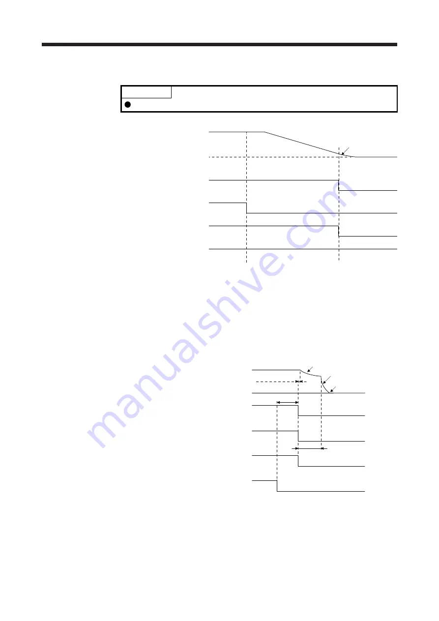
(b) Forced stop 2 on/off
POINT
In the torque control mode, the forced stop deceleration function is not available.
ON
ON
OFF
(Note 2)
Model speed command 0
and equal to or less than
zero speed
ON
OFF
OFF
EM2 (Forced stop 2)
MBR
(Electromagnetic
brake interlock)
ON (no alarm)
OFF (alarm)
Base circuit
(Energy supply to
the servo motor)
0 r/min
Servo motor speed
ALM (Malfunction)
(Note 1)
Note 1. ON: Electromagnetic brake is not activated.
OFF: Electromagnetic brake has been activated.
2. The model speed command is a speed command generated in the servo amplifier for forced stop
deceleration of the servo motor.
(c) Alarm occurrence
The operation status during an alarm is the same as section 3.8.
(d) Both main and control circuit power supplies off
MBR
(Electromagnetic
brake interlock)
(Note 2)
ON
OFF
Base circuit
ON
OFF
Alarm
[AL.10 Undervoltage]
No alarm
Alarm
Approx. 10 ms
Dynamic brake
Dynamic brake
+ Electromagnetic brake
Electromagnetic brake
(Note 1)
Operation delay time of
the electromagnetic brake
Servo motor speed
ON
OFF
Main circuit
Control circuit Power supply
0 r/min
Note 1. Variable according to the operation status.
2. ON: Electromagnetic brake is not activated.
OFF: Electromagnetic brake has been activated.
Summary of Contents for MR-J4
Page 9: ...A 8 MEMO ...
Page 19: ...10 MEMO ...
Page 73: ...1 FUNCTIONS AND CONFIGURATION 1 54 MEMO ...
Page 155: ...3 SIGNALS AND WIRING 3 76 MEMO ...
Page 199: ...4 STARTUP 4 44 MEMO ...
Page 289: ...6 NORMAL GAIN ADJUSTMENT 6 24 MEMO ...
Page 335: ...8 TROUBLESHOOTING 8 8 MEMO ...
Page 357: ...9 OUTLINE DRAWINGS 9 22 MEMO ...
Page 517: ...12 ABSOLUTE POSITION DETECTION SYSTEM 12 30 MEMO ...
Page 617: ...16 USING A DIRECT DRIVE MOTOR 16 20 MEMO ...
Page 641: ...17 FULLY CLOSED LOOP SYSTEM 17 24 MEMO ...
Page 725: ...18 MR J4 03A6 SERVO AMPLIFIER 18 84 MEMO ...
Page 763: ...APPENDIX App 38 ...
Page 789: ...MEMO ...
Page 793: ......


