4.6 Gain adjustment
81
4.6 Gain adjustment
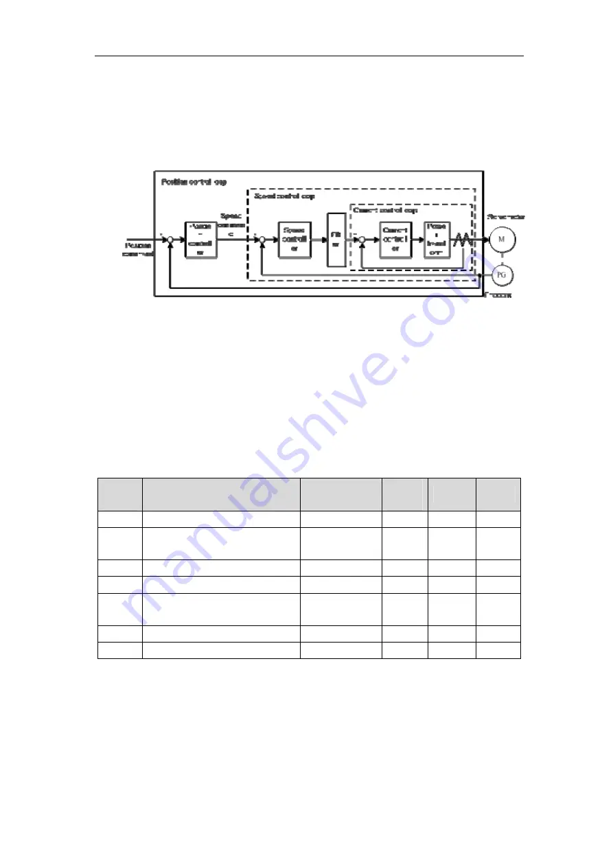
The servo driver includes the current control loop, the speed control loop and the position
control loop. The control diagram is as follows:
Theoretically, the inner control loop bandwidth must be higher than the outer loop; otherwise,
the entire control system will be unstable and creates the vibration or worse response. Therefore,
the relations of the bandwidth of the three control loops are as follows:
Bandwidth of the current loop>bandwidth of the speed loop>bandwidth of the of the
position loop
Because the current control loop of the servo driver is already adjusted in an optimum
condition, the only parameters of speed and position control loops have to be adjusted by the user.
4.6.1 Gain parameters
The parameters related to the gain are:
Parame
ter
Name
Range
Default
value
Unit
Usage
P005
First gain of speed loop
1
~
3000 40 Hz
P,S
P006
First integral time constant of
speed loop
1.0
~
1000.0 20.0 ms P,S
P009
First gain of position loop
1
~
1000 40 1/s P
P010
Second gain of speed loop
1
~
3000 40 Hz
P,S
P011
2nd integral time constant of
speed loop
1.0
~
1000.0 20.0 ms P,S
P013
Second gain of position loop
1
~
1000 40 1/s P
P017
Ratio of load inertia
0.0
~
200.0 1.0 times P,S
The definition of symbol as follows:
K
v
:
The gain of speed loop;
Summary of Contents for EP3 AC Series
Page 1: ...Wuhan Maxsine Electric Co Ltd...
Page 12: ...Chapter 1 Product inspection and installment 2 1 2 Product nameplate...
Page 16: ...Chapter 1 Product inspection and installment 6...
Page 40: ...Chapter 2 Wiring 30 2 5 2 Wiring diagram for speed or torque control...
Page 57: ...3 7 Resume the parameter default values 47 Remarks...
Page 124: ...Chapter 4 Running 114 Remarks...
Page 221: ...198 Chapter 8 Specifications 8 1 Types of servo driver...
Page 231: ...8 5 Types of servo motor 8 5 Types of servo motor...


