4.5 Motion mode
79
NEXT: After this path is finished and the delay time is reached, it will load the next path
automatically, which is triggered by the next CTRG signal.
INS: it allows to be interrupted by the next path when this path is executed.
The following chart shows how to set NPRC to choose the next path.
NPRC Next
path
Bit7
Bit 6
Bit 5
0 0 0
Path
1
(P400
、
P401
;
P500
、
P501)
0 0 1
Path
2
(P402
、
P403
;
P502
、
P503)
0 1 0
Path
3
(P404
、
P405
;
P504
、
P505)
0 1 1
Path
4
(P406
、
P407
;
P506
、
P507)
1 0 0
Path
5
(P408
、
P409
;
P508
、
P509)
1 0 1
Path
6
(P410
、
P411
;
P510
、
P511)
1 1 0
Path
7
(P412
、
P413
;
P512
、
P513)
1 1 1
Path
8
(P414
、
P415
;
P514
、
P515)
4. Path data
Path data is valid when path TYPE is 1.
For example, path 1 data is path target position, which consists of parameter P500 and
P501.
Path 1 data = P501×2
16
+ P500
The data unit is PEU, which is equal to the resolution of encoder.
The target position is confirmed relating to the position after DSZR. Take the position after
DSZR as origin.
4.5.5 Motion path explanation
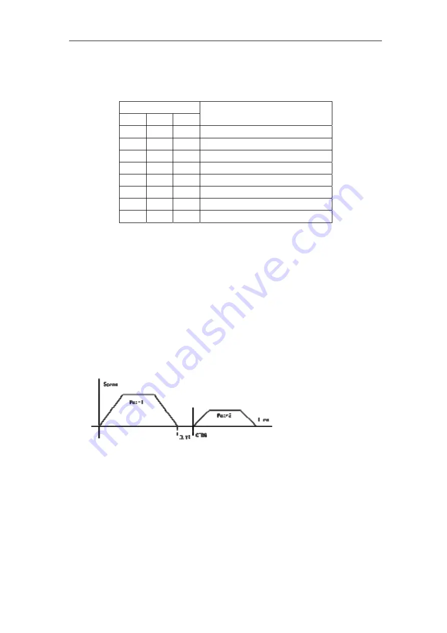
1. Internal sequence
Path1: position command (TYPE=1).Execute the next one automatically (NEXT=1).DLY
has been set.
Path 2: position command (TYPE=1)
Note: DLY begins to count when the command has been finished.Need CTRG to trigger.
Summary of Contents for EP3 AC Series
Page 1: ...Wuhan Maxsine Electric Co Ltd...
Page 12: ...Chapter 1 Product inspection and installment 2 1 2 Product nameplate...
Page 16: ...Chapter 1 Product inspection and installment 6...
Page 40: ...Chapter 2 Wiring 30 2 5 2 Wiring diagram for speed or torque control...
Page 57: ...3 7 Resume the parameter default values 47 Remarks...
Page 124: ...Chapter 4 Running 114 Remarks...
Page 221: ...198 Chapter 8 Specifications 8 1 Types of servo driver...
Page 231: ...8 5 Types of servo motor 8 5 Types of servo motor...


