1.2 Names and Functions of Parts
10
1.2
Names and Functions of Parts
Front Panel
CF Card slot
Handle
Left Side
Printer
Display
(LCD)
Right Side
Various Input Modules
(For details, see the documen-
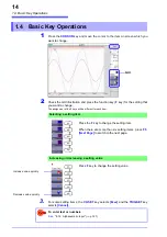
tation of the respective input
module.)
Power Inlet
Connect the supplied power
cord here.(
GND Terminal (Functional Earth)
Connect to Earth ground.(
USB Connector (Type B)
Connect a USB cable here.
(
USB Connector (Type A)
Connect a USB memory stick
here. (
100BASE-TX Connector
Connect a LAN cable here.
(
Standard LOGIC terminals
Input connectors for proprietary
logic probes. (
External control terminals
An external sampling signal can be
connected here. (
Allows control of the instrument.
POWER Switch
Turns the instrument on and off.
: Power On
: Power Off (
Operating Keys
Summary of Contents for 8847
Page 1: ...MEMORY HiCORDER Instruction Manual 8847 December 2010 Revised edition 4 8847A981 04 10 12H ...
Page 2: ......
Page 18: ...Operating Precautions 8 ...
Page 26: ...1 4 Basic Key Operations 16 ...
Page 74: ...4 4 Waveform Observation 64 ...
Page 98: ...5 5 Managing Files 88 ...
Page 110: ...6 6 Miscellaneous Printing Functions 100 ...
Page 126: ...7 8 Seeing Block Waveforms 116 ...
Page 160: ...8 10 Making Detailed Settings for Input Modules 150 ...
Page 198: ...10 6 Numerical Calculation Type and Description 188 ...
Page 296: ...15 7 Controlling the Instrument with Command Communications LAN USB 286 ...
Page 304: ...16 2 External I O 294 ...
Page 362: ...Appendix 5 FFT Definitions A28 ...
Page 368: ...Index Index 6 ...
Page 369: ......
Page 370: ......
Page 371: ......


