15.4 Transferring Data to the PC
276
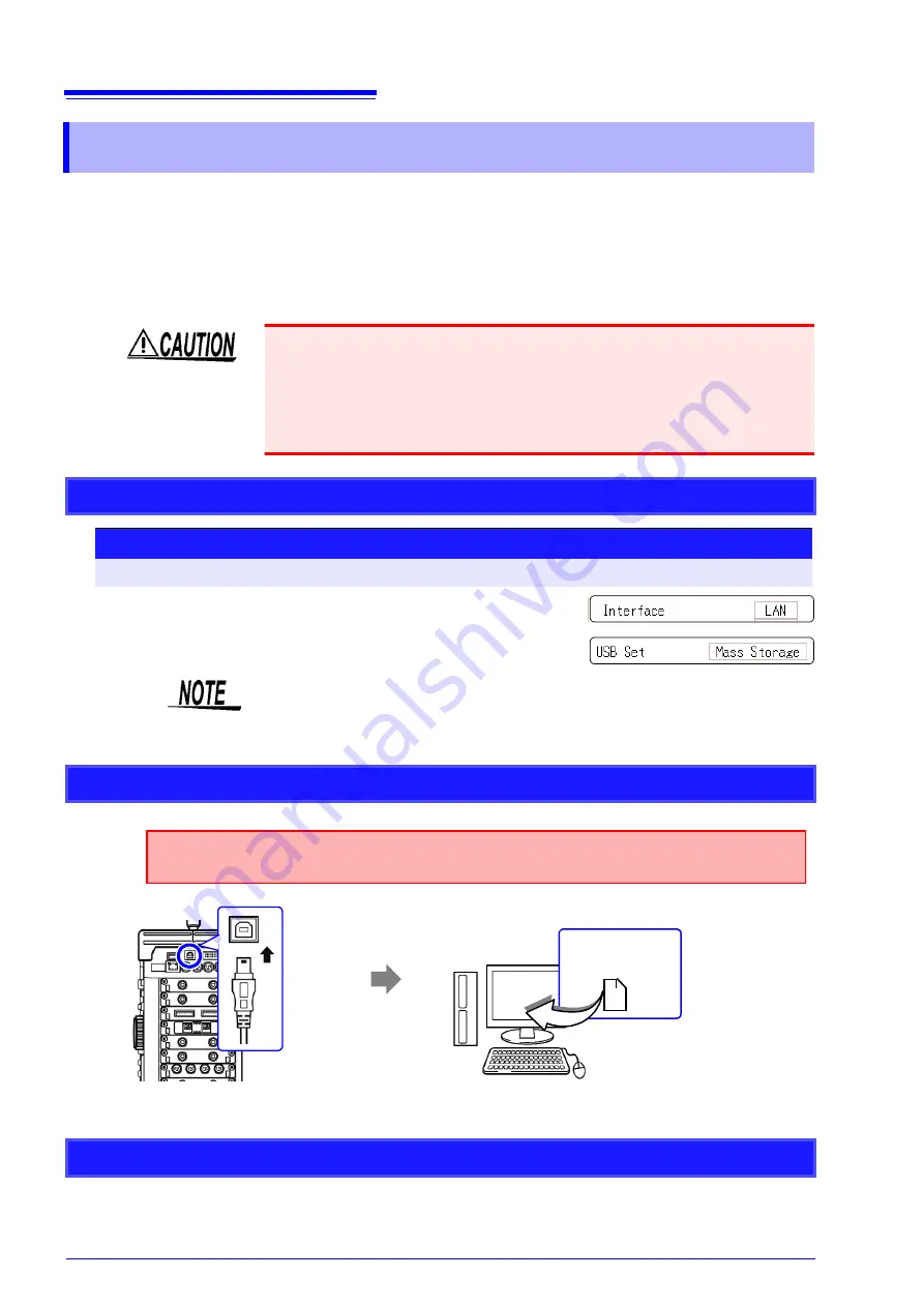
The supplied USB Cable can be used to transfer data from the HDD to a PC.
For information on how to use the supplied application software for data analysis,
refer to the application's Help function.
See:
Installing and starting the application software:"15.5"(
Supported hardware
PC capable of running Windows 2000, XP, or Vista
When the connection is established, the PC will recognize the instrument as a
removable disk. The PC can now access data on the HDD of the instrument.
To disconnect the USB Cable of the instrument from a PC that is currently run-
ning, use the "Safely Remove Hardware" icon and follow the prescribed steps.
15.4 Transferring Data to the PC
• During data transfer, do not disconnect the USB cable. Otherwise the transfer
will not be completed normally.
• Ground the instrument and the PC at the same ground point. If the equipment
is connected to different ground points, an electric potential will exist between
the PC ground and the instrument ground. If a USB Cable is connected in this
condition, operation problems and damage can occur.
Instrument Settings
Procedure
To open the screen: Press the
SYSTEM
key
→
[Interface]
sheet
1
Move the cursor to the
[Interface]
, and select
[LAN]
.
2
Move the cursor to the
[USB Set]
, and select
[Mass Storage]
.
Operations to the USB memory stick or HDD from the instrument are restricted
during
[Mass Storage]
.Furthermore, the printer prints at Slow/Fine, regardless
of the print speed setting.
Connecting the USB Cable
Insert the plug of the USB
cable into the USB port on
the instrument, observing
correct orientation of the
plug.
1
Plug the other end of the USB cable
into a USB port on the PC.
2
Preparations
Stop measurement and make sure that the File screen is not displayed.
Removable disk
USB Connector
(Type B)
Disconnecting the USB Cable
Summary of Contents for 8847
Page 1: ...MEMORY HiCORDER Instruction Manual 8847 December 2010 Revised edition 4 8847A981 04 10 12H ...
Page 2: ......
Page 18: ...Operating Precautions 8 ...
Page 26: ...1 4 Basic Key Operations 16 ...
Page 74: ...4 4 Waveform Observation 64 ...
Page 98: ...5 5 Managing Files 88 ...
Page 110: ...6 6 Miscellaneous Printing Functions 100 ...
Page 126: ...7 8 Seeing Block Waveforms 116 ...
Page 160: ...8 10 Making Detailed Settings for Input Modules 150 ...
Page 198: ...10 6 Numerical Calculation Type and Description 188 ...
Page 296: ...15 7 Controlling the Instrument with Command Communications LAN USB 286 ...
Page 304: ...16 2 External I O 294 ...
Page 362: ...Appendix 5 FFT Definitions A28 ...
Page 368: ...Index Index 6 ...
Page 369: ......
Page 370: ......
Page 371: ......


