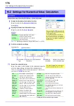
10.2 Settings for Numerical Value Calculation
178
Parameter table________________________________________________
Calculation Type
Parameter
Parameter description
Period
Frequency
Pulse Width
Pulses
Duty Ratio*
Time Diff
Phase Diff
*: Level and
Filter only
L (Level)
Calculation is based on the interval (time) when this level is crossed.
F (Filter)
Only when the measurement signal has crossed the level and has not crossed the
level again within the specified filter width, it is taken as a valid event. This is useful
to exclude level crossing events due to noise.
S (Slope(
↑
,
↓
))
Calculation is based on the interval (time) when the level is crossed.
Depending on this setting, either crossing on the upward slope (
↑
) or downward
slope (
↓
) is used for calculation.
Risetime
Falltime
P (%)
Determines which section of the waveform between the upper and lower limits is
used for risetime (or falltime) calculation. The range is narrowed from the upper and
lower limit values by the percentage set here.
Time to Lev
L (Level)
Calculates the time specified level is crossed.
F (Filter)
Only when the measurement signal has crossed the level and has not crossed the
level again within the specified filter width, it is taken as a valid event. This is useful
to exclude level crossing events due to noise.
S (Slope(
↑
,
↓
))
Determines whether the time is calculated until the signal crosses the specified lev-
el on the upward slope or on the downward slope.
Lev-Time
Time or Measure (Calcula-
tion results)
Specifies the time for calculating the measurement value, using the trigger position
as zero.
To use the numerical calculation result, specify the numerical calculation number.
The range specified by A/B cursors is not available.
Calculation
Numerical Calculation No.
Sets the numerical calculation number.
+
,
-
,
×
,
÷
Sets the operators for the four arithmetic operations.
• Depending on the signal waveform, calculation values for the Period, Fre-
quency, Risetime, and Falltime parameters may not be displayed.
• When Scaling is enabled, the waveform data are scaled before numerical cal-
culation. The units for parameter values are derived from the units set for the
Scaling function.
See:
About Scaling: "8.5 Converting Input Values (Scaling Function)" (
Summary of Contents for 8847
Page 1: ...MEMORY HiCORDER Instruction Manual 8847 December 2010 Revised edition 4 8847A981 04 10 12H ...
Page 2: ......
Page 18: ...Operating Precautions 8 ...
Page 26: ...1 4 Basic Key Operations 16 ...
Page 74: ...4 4 Waveform Observation 64 ...
Page 98: ...5 5 Managing Files 88 ...
Page 110: ...6 6 Miscellaneous Printing Functions 100 ...
Page 126: ...7 8 Seeing Block Waveforms 116 ...
Page 160: ...8 10 Making Detailed Settings for Input Modules 150 ...
Page 198: ...10 6 Numerical Calculation Type and Description 188 ...
Page 296: ...15 7 Controlling the Instrument with Command Communications LAN USB 286 ...
Page 304: ...16 2 External I O 294 ...
Page 362: ...Appendix 5 FFT Definitions A28 ...
Page 368: ...Index Index 6 ...
Page 369: ......
Page 370: ......
Page 371: ......


