3.4 Setting Measurement Configuration
45
3
Chapte
r 3
Measur
em
en
t Proced
ure
_______________________________________________________________
• The timebase and sampling rate can be set independently. The sampling rate
is selected depending on the timebase setting.
• When the following timebase values are selected, displayed waveforms are
compressed in the horizontal (time axis) direction as shown.
20 ms/div
→
x1/2
10 ms/div
→
x1/5
_______________________________________________________________
Common
To automatically set the time axis range
When you press the
AUTO
key, a suitable time range for the input sig-
nal is selected and measurement starts. (This applies only to the
Memory Function.)
See:
"3.7 Measurement With Automatic Range Setting (Auto-Ranging Func-
tion)" (
To minimize noise during measurement
If the sampling rate is set too fast, when the input waveform ampli-
tude is small, the difference between maximum and minimum values
may become quite large as a result of sudden impulses such as
noise. To prevent such phenomena, select a slower sampling rate or
enable the input module's lowpass filter (
The data refresh rate is not allowed to exceed the maximum sampling rate of the
input module.
During the period when data are not updated, the same data are measured,
resulting in a stair-shaped waveform. Even when the same signal is sampled
simultaneously by two units, the data may differ due to differences in sampling
rate, frequency bandwidth, and frequency response.
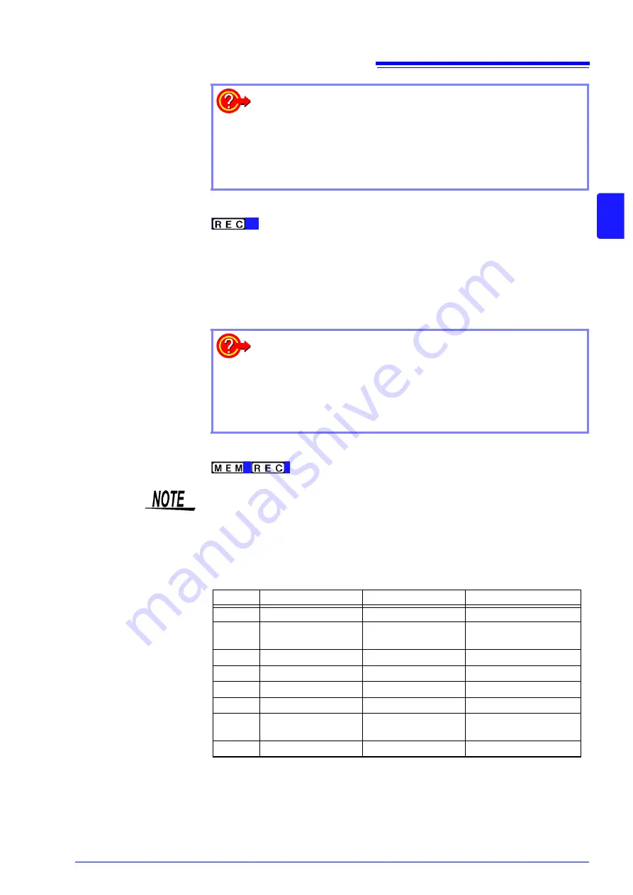
Data refresh rate for various units
Module
Max. time axis range
Max. sampling setting
See
8966
5
μ
s/div
50 ns (20 MS/s)
-
8967
Dependent on data re-
fresh setting
Dependent on data re-
fresh setting
See:
8968
100
μ
s/div
1
μ
s (1 MS/s)
-
8969
500
μ
s/div
5
μ
s (500 ks/s)
-
8970
Dependent on setting
Dependent on setting
See:
8971
100
μ
s/div
1
μ
s (1 MS/s)
See:
8972
Dependent on re-
sponse setting
Dependent on re-
sponse setting
See:
8973
5
μ
s/div
50 ns (20 MS/s)
-
Summary of Contents for 8847
Page 1: ...MEMORY HiCORDER Instruction Manual 8847 December 2010 Revised edition 4 8847A981 04 10 12H ...
Page 2: ......
Page 18: ...Operating Precautions 8 ...
Page 26: ...1 4 Basic Key Operations 16 ...
Page 74: ...4 4 Waveform Observation 64 ...
Page 98: ...5 5 Managing Files 88 ...
Page 110: ...6 6 Miscellaneous Printing Functions 100 ...
Page 126: ...7 8 Seeing Block Waveforms 116 ...
Page 160: ...8 10 Making Detailed Settings for Input Modules 150 ...
Page 198: ...10 6 Numerical Calculation Type and Description 188 ...
Page 296: ...15 7 Controlling the Instrument with Command Communications LAN USB 286 ...
Page 304: ...16 2 External I O 294 ...
Page 362: ...Appendix 5 FFT Definitions A28 ...
Page 368: ...Index Index 6 ...
Page 369: ......
Page 370: ......
Page 371: ......


