background image

15.7  Controlling the Instrument with Command Communications (LAN/USB)

285

12

Chapt

er 15  

Connec

ti

on to a 

Comput

er

15

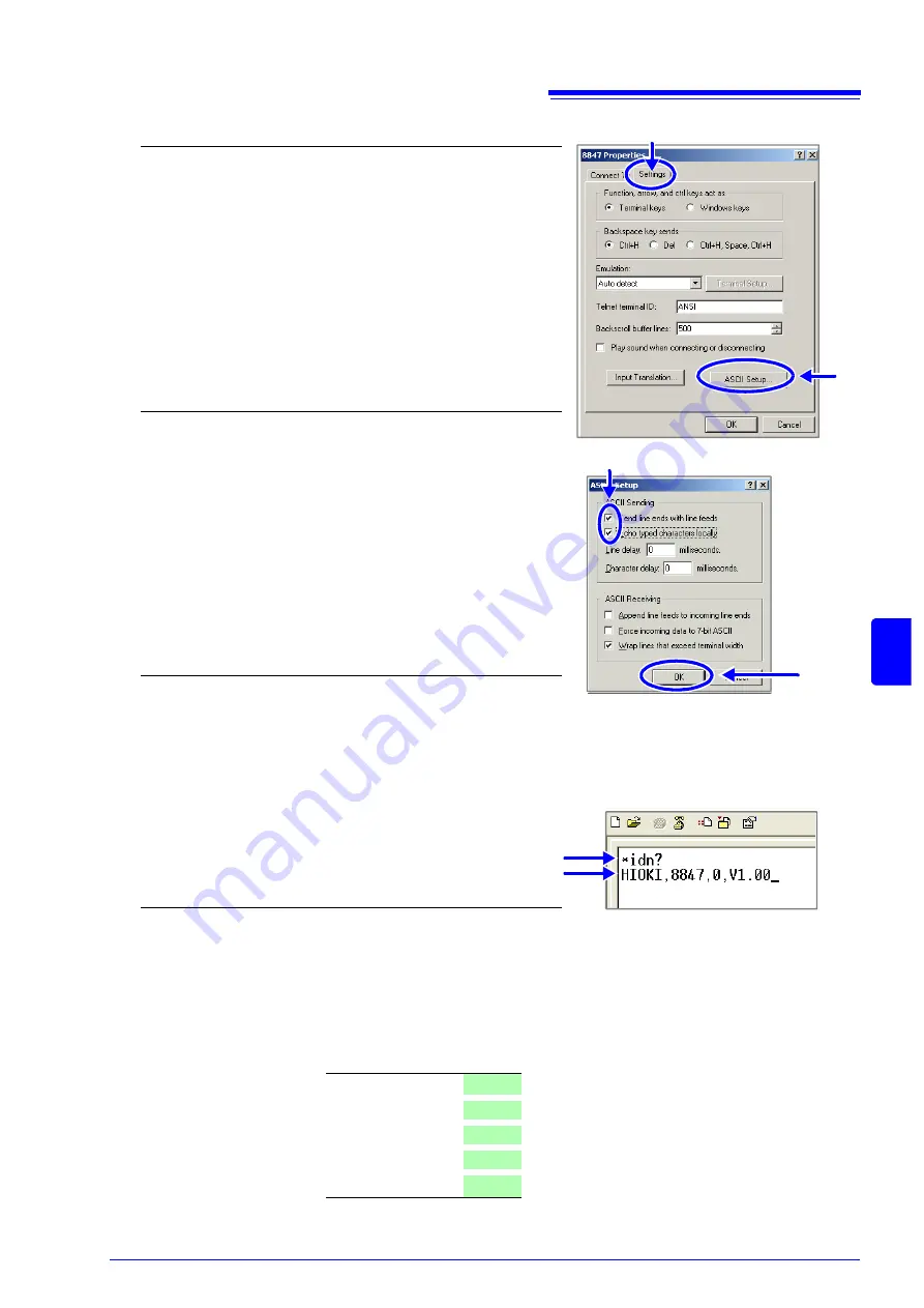
When using the USB interface for command communications, the following differences exist, compared
to using a LAN connection.

• Select 

[COMX]

 as 

[Connect using]

 in 3-1. (X is a letter that will differ depend-

ing on the environment.)

• After completing 3-4., make the following settings.

4

Make detailed connection settings.

1. Select 

[Properties]

 in the 

[File]

 menu.

The Properties dialog for the specified connection name ap-
pears.

2. Click the 

[Settings]

 tab.

3. Click the 

[ASCII Setup...]

 button.

The 

[ASCII Setup]

 dialog appears.

5

Make detailed settings

1. Check the 

[Send line ends with line feeds]

 and

[Echo typed characters locally]

 check boxes.

2. Click the 

[OK]

 button to return to the Properties

dialog.

3. Click the 

[OK]

 button to return to the HyperTermi-

nal window.

6

Try sending a command.

Enter "*idn?" and press the Enter key.

A response is returned from the instrument.

2

3

Command

Response

1

2

Bits per second

19200

Data bit

8

Parity

None

Stop bit

1

Flow control

None

Summary of Contents for 8847

Page 1: ...MEMORY HiCORDER Instruction Manual 8847 December 2010 Revised edition 4 8847A981 04 10 12H ...

Page 2: ......

Page 3: ...2 1 Install an input module 18 2 2 Connecting Cords 20 2 3 Recording Media Preparation 28 2 3 1 Storage Media Inserting a CF Card and USB Memory Stick 28 2 3 2 Formatting Storage Media 30 2 4 Loading Recording Paper 31 2 5 Supplying Power 33 2 5 1 Connecting the Power Cord 33 2 5 2 Grounding the Instrument s Functional Earth 33 2 5 3 Turning the Power On and Off 34 2 6 Setting the Clocks 35 2 7 Ad...

Page 4: ...Configuration 61 4 3 Starting and Stopping Measurement 62 4 4 Waveform Observation 63 4 4 1 Saving and Printing Waveform 63 Chapter 5 Saving Loading Data Managing Files _________65 5 1 Data capable of Being Saved Loaded 67 5 2 Saving Data 68 5 2 1 Save Types and Workflow 68 5 2 2 Automatically Saving Waveforms 69 5 2 3 Saving Data Selectively SAVE Key 74 5 3 Loading Data 77 5 4 Automatically Loadi...

Page 5: ...osition 106 7 3 2 Scrolling With Jog and Shuttle Knobs Scroll 106 7 3 3 Moving the Position Jump Function 107 7 4 Performing Waveform X Y Synthesis 108 7 5 Magnifying and Compressing Waveforms 110 7 5 1 Magnifying and Compressing Horizontal Axis Time Axis 110 7 5 2 Zoom Function Magnifying a Section of the Horizontal Axis Time Axis 111 7 5 3 Magnifying and Compressing Vertical Axis Voltage Axis 11...

Page 6: ...ngs for the 8967 Temp Unit 142 8 10 4 Settings for the 8969 Strain Unit 144 8 10 5 Settings for the 8970 Freq Unit 145 8 10 6 Settings for the 8971 Current Unit 148 8 10 7 Settings for the 8972 DC RMS Unit 149 Chapter 9 Trigger Settings ___________________________151 9 1 Setting Workflow 152 9 2 Setting the Trigger Mode 153 9 3 Triggering by Analog Signals 154 9 3 1 Analog Trigger Settings and Typ...

Page 7: ...lation 192 11 2 1 Displaying the waveform calculation results 193 11 2 2 Setting constants 195 11 2 3 Changing the display method for calculated waveforms 196 11 3 Waveform Calculation Operators and Results 198 Chapter 12 Memory Division Function __________________ 201 12 1 Recording Settings 203 12 2 Display Settings 204 Chapter 13 FFT Function _____________________________ 207 13 1 Overview and ...

Page 8: ...o a Computer __________________259 15 1 LAN Settings and Connection Before Using FTP Internet Browser Command Communications 260 15 1 1 Making LAN Settings at the Instrument 260 15 1 2 Connecting Instrument and PC With LAN Cable 263 15 2 Performing Remote Operations on the Instrument Use an Internet Browser 265 15 2 1 Making HTTP Settings on the Instrument 265 15 2 2 Connecting to the Instrument W...

Page 9: ...16 2 5 External Trigger terminal EXT TRIG 293 Chapter 17 Specifications_____________________________ 295 17 1 General Specifications 295 17 2 Measurement Specifications 298 17 2 1 Memory Function 298 17 2 2 Recorder Function 298 17 2 3 X Y Recording 299 17 2 4 FFT Function 299 17 3 Trigger Section 300 17 4 File Specifications 301 17 5 Built In Functions 302 17 6 Input Modules Specifications 304 17...

Page 10: ...____________________ A 1 Appendix 1 Default Values for Major Settings A 1 Appendix 2 Reference A 2 Appendix 2 1 Waveform File Sizes A 2 Appendix 2 2 Setting Configuration and Image Data File Sizes A 5 Appendix 2 3 Timebase and Maximum Recordable Time A 6 Appendix 2 4 Maximum record length and number of divisions Memory division function A 8 Appendix 2 5 Scaling Method When Using Strain Gauges A 9 ...

Page 11: ...Applying a Manual Trigger p 165 Adding Comments p 118 Freely Setting the Waveform Display p 49 Converting Input Values p 128 Copying Settings to Other Channels p 139 Suppressing Noise Low pass filter p 54 Composing X Y Waveforms p 108 Locking the Keys KEY LOCK p 11 Initializing a CF card p 30 Scaling During Measurement Using a Current Clamp p 130 Basic Workflow p 17 p 37 p 56 p 34 p 89 p 101 Conne...

Page 12: ... it fails to operate according to the specifications contact your dealer or Hioki representative Introduction Document Description 1 Measurement Guide Read first Offers an introduction to the Memory HiCorder s basic mea suring method for first time users 2 Instruction Manual This document Contains explanation and instructions regarding the instru ment s operating method and functions Confirming Pa...

Page 13: ...ibility for accidents or injuries not resulting directly from instrument defects Safety Symbols In the manual the symbol indicates particularly important infor mation that the user should read before using the instrument The symbol printed on the instrument indicates that the user should refer to a corresponding topic in the manual marked with the symbol before using the relevant function Indicate...

Page 14: ...nder Arti cle 11 2 of Directive 2002 96 EC WEEE This symbol indicates that the product conforms to safety regulations set out by the EC Directive Notation Indicates the prohibited action p Indicates the location of reference information Indicates quick references for operation and remedies for troubleshoot ing Indicates that descriptive information is provided below Menus commands dialogs buttons ...

Page 15: ...CAT III Primary electrical circuits of heavy equipment fixed installations con nected directly to the distribution panel and feeders from the distribution panel to outlets CAT IV The circuit from the service drop to the service entrance and to the power meter and primary overcurrent protection device distribution panel Higher numbered categories correspond to electrical environments with greater m...

Page 16: ...ent should be operated only with the bottom or rear side downwards Vents must not be obstructed Do not install the instrument at a slanted angle Operating Precautions Before Use Before using the instrument make sure that the insulation on the connection cords and connection cords is undamaged and that no bare conductors are improperly exposed Using the instrument in such conditions could cause an ...

Page 17: ... cable may result in incorrect measurements due to poor connection or other reasons Handling the CD Always hold the disc by the edges so as not to make fingerprints on the disc or scratch the printing Do not wet the disc with volatile alcohol or water as there is a possibility of the label printing disappearing To write on the disc label surface use a spirit based felt pen Do not use a ball point ...

Page 18: ...Operating Precautions 8 ...

Page 19: ...Easily take the unit anywhere Easy loading of recording paper High speed printing One touch insertion allows quick and trouble free operation Immediately ready for mea surement after power on Logic modules allow measurement in 64 channels Ideal for multi point measurements High speed sampling 20 Ms s Enables responsive evaluation and analysis For best measurement precision a warm up period of abou...

Page 20: ... Terminal Functional Earth Connect to Earth ground p 33 USB Connector Type B Connect a USB cable here p 278 USB Connector Type A Connect a USB memory stick here p 28 100BASE TX Connector Connect a LAN cable here p 259 Standard LOGIC terminals Input connectors for proprietary logic probes p 20 External control terminals An external sampling signal can be connected here p 287 Allows control of the i...

Page 21: ...r up down left and right on the screen KEY LOCK Press and hold the right and left CURSOR keys for three seconds to disable key operations To cancel key lock hold the keys again for three seconds TRIG SET key Displays the trigger settings window on the Waveform screen p 151 CH SET key Displays the channel settings window on the Waveform screen p 49 SYSTEM key Displays the System screen p 255 CHAN k...

Page 22: ...al calculation of waveform data Each push of the STATUS key toggles between the following two sheets Status sheet Num Calc sheet Memory Div sheet Wave Calc sheet Channel Screen This screen serves for making channel settings scaling settings and comment settings Each push of the CHAN key cycles through the following sheets Unit List sheet Each Ch sheet Scaling sheet Comment sheet System Screen This...

Page 23: ...igger event p 151 Vertical axis display Shows the value per increment for each channel This is linked to the range set ting p 52 Upper and lower limit The upper and lower limit values for each channel are shown here p 114 Scroll bar The stored waveform is indicated by a red bar and the displayed waveform by a blue frame p 106 Media icon Shows the media status p 28 Elements common to Status screen ...

Page 24: ... each item 3 For some setting items the CH SET key selects Exec and the TRIG SET key selects Cancel 1 4 Basic Key Operations GUI Selecting a setting item Press the F key to change the setting item When there are more than six setting items press F5 Next Page to switch to the next page Increasing or decreasing a setting value Press F key to change the setting value Increase value quickly Decrease v...

Page 25: ...rsor Pos Help sheet is displayed at the cursor posi tion You can scroll the information using the cursor up down keys and the Jog knob You can change the size of the Help sheet with the CH SET key Available settings are full top half and bottom half The example above is for top half Each push of the HELP key cycles through the following settings Cursor Position Help Help off 1 4 1 Example for Usin...

Page 26: ...1 4 Basic Key Operations 16 ...

Page 27: ... Probes and cables will differ depending on the measurement purpose 5 Insert media CF Card USB memory stick p 28 6 Load recording paper p 31 7 Connect the power cord p 33 8 Ground the Functional Earth of this instrument For measurement in noise prone environments p 33 9 Turn the power on p 34 10 Setting the clock p 35 11 Perform zero adjust p 36 When preparations are complete let s start a measure...

Page 28: ...n this instrument Measurements made without a blank panel installed may fail to meet specifica tions because of temperature instability within the instrument For information on analog channel accuracy when using logic channels see 8 10 Making Detailed Settings for Input Modules p 140 Required item One Phillips head screwdriver 1 Turn the instrument s POWER switch Off 2 With attention to the orient...

Page 29: ...ion list System Information Blank panel Measurements made without a blank panel installed may fail to meet specifications because of temperature instability within the instrument If not installing another input module after removal Right Side Using the Phillips screwdriver tighten the two mount ing screws Ch15 Ch1 Ch16 Ch2 Ch3 Ch4 LA LB LC LD 1 4 1 4 1 4 1 4 LA LB LC LD 1 4 1 4 1 4 1 4 Module 1 Mo...

Page 30: ...not touch any input termi nals on the VT PT CT or the instrument when they are in operation Do not permanently connect the device in an environment where voltage surges exceeding the maximum input voltage may occur Failure to observe this precaution could result in damage to the device and personal injury Connecting to the BNC jacks on input modules When disconnecting the BNC connector be sure to ...

Page 31: ...100 1 Probe Example 9322 Differen tial Probe Measuring Voltage Connect to the BNC jack on an input mod ule A power cord option or AC adapter may be required depending on the input module used Example 8966 Analog Unit Required item One of the above cables BNC jack Connect to BNC jack Lock Input module connector guide pins BNC plug slots Connect to the measurement object Connecting the cable 1 Conne...

Page 32: ...onnection Cord Maximum input voltage 300 V Small alligator clip type L9217 Connection Cord Maximum input voltage 300 V For measuring BNC output If the voltage to be measured exceeds the maximum input rating of the input module being used 9322 Differential Probe Example 9322 Differen tial Probe Measuring frequency number of rotations and Count Connect to the BNC jack on an input mod ule A power cor...

Page 33: ...th approx 10 mm 2 Push the blade of a flat screwdriver into the button on the terminal block of the input module 3 Insert each thermocouple wire into the appropriate terminal hole while press ing the button Confirm proper polarity 4 Release the button The thermocouple is connected 5 Attach to the measurement object To remove the thermocouple Hold the button while pulling the ther mocouple wire out...

Page 34: ...onnect the strain gauge transducer to the conversion cable 3 Attach to the measurement object Example Connecting the 9769 Conversion Cable with the supplied conversion cable Required item 9769 Conversion Cable Strain Gauge Converter Connect to input module s terminal Connect to the Strain Gauge Converter 3 2 1 Bridge voltage 2 V is supplied Connector pinout of 9769 on sensor side Metal shell is co...

Page 35: ...ntil it locks 2 Align the grooves of the conversion cable connector and the plug of the clamp on sensor to be used Insert the plug until it locks 3 Connect the clamp sensor to the item to be measured To disconnect the conversion cable Slide the plug to release the lock and then unplug the cable Example When connecting the 9272 10 Clamp On Sensor Required item 9318 Conversion Cable 9272 Clamp On Se...

Page 36: ...e to the measurement object or this instrument because of current flow through the logic probes resulting from potential difference between the grounds of the different wiring systems To avoid these problems we recommend the following connection pro cedure Maximum logic probe input voltages are as follows Do not measure if the maximum voltage would be exceeded as damage the instrument or personal ...

Page 37: ...o the measurement object Right Side Example Connecting the 9327 Logic Probe 1 Connect the logic probe by aligning the groves on the plug and a LOGIC termi nal 2 Connect to the measurement object Required item 9327 Logic Probe Connect to LOGIC Terminals LOGIC terminals 2 1 ...

Page 38: ...tic electricity Exercise care when using such products because static electricity could damage the USB memory stick or cause malfunction of the instrument With some USB memory sticks the instrument may not start up if power is turned on while the USB memory stick is inserted In such a case turn power on first and then insert the USB memory stick It is recommended to try out opera tion with a USB m...

Page 39: ...gain before inserting in the CF card all the way in Removing a CF Card Press the Eject button When the button pops out press it again to eject the CF Card CF Card Slot Inserting a USB memory stick Ensure correct orientation of the USB memory stick and push it all the way into the connector Remove a USB memory stick Verify that the unit is not accessing the USB memory stick for saving or load ing d...

Page 40: ... used storage media deletes all the information on the stor age media and that deleted information is unrecoverable Procedure To open the screen Press the FILE key File screen 1 Insert the storage media 2 Select Next Page Select Format The cursor moves to the Format Target item 3 Select the storage media to format and select Exec The specified storage media is formatted A confirmation window will ...

Page 41: ...ng is not possible if the front and back of the recording paper are reversed Always use the paper cutter to cut the printed paper Excessive paper dust can accumulate on the roller if the paper is cut by the print head Handling and Storing Recording Paper The recording paper is thermally and chemically sensitized Observe the follow ing precautions to avoid paper discoloration and fading Avoid expos...

Page 42: ...per is mounted without attaching the paper roll axle the printer cover may not open and the printer may be damaged 3 Pull the paper out and then close the printer cover while pushing the paper against the side of the cover The surface of the paper may become sticky from the residue left behind by the adhesive tape and cause the printing on that area to become unreadable After loading the paper fee...

Page 43: ...tage or frequency range is exceeded or if a source with square wave output is used the instrument may be fatally damaged and an electrical accident may occur 1 Rated mains supply voltage is 100 to 240 VAC 2 Rated mains supply frequency is 50 60 Hz 3 Sine wave output Do not use sources with unstable output To avoid electrical accidents and to maintain the safety specifications of this instrument co...

Page 44: ...rting Measurement To obtain precise measurements provide about 30 minutes warm up after turn ing power on to allow the internal temperature of the input modules to stabilize After that perform zero adjustment before taking measurements Turn the POWER switch off When power is turned on again the display appears with the settings that existed when power was last turned off When the Auto Setup functi...

Page 45: ...ting Year Month Day Time setting Hour Minutes Seconds Procedure To open the screen Press the SYSTEM key Init sheet 1 Move the cursor to the Clock item 2 Select the digit to change and set the numeric value 3 When you select Apply while the cursor is on the Clock item the clock is set to the cur rent date and time values The date and time indication is shown at the top right of the screen The instr...

Page 46: ...ting point of an opera tional amprifier Drift can occur due to changes in temperature and due to compo nent aging over a period of use 2 7 Adjusting the Zero Position Zero Adjust To obtain precise measurements provide about 30 minutes warm up after turning power on to allow the internal temperature of the input modules to stabilize Note that zero adjust cannot be performed during a measurement Dur...

Page 47: ... at the input Take the connection method into consider ation and make sure that the rating is not exceeded Input module Maximum rated input voltage Maximum rated voltage versus ground 8966 Analog Unit 400 VDC 300 VAC DC 8967 Temp Unit 300 VAC DC 8968 High Resolution Unit 400 VDC 300 VAC DC 8969 Strain Unit 33 V rms 70 VDC 8970 Freq Unit 400 VDC 300 VAC DC 8971 Current Unit Not insulated 8972 DC RM...

Page 48: ...g Recording Roll Mode p 124 8 3 Displaying New Waveforms Over Past Waveforms Overlay p 125 8 4 Setting Channels to Use Extending the Recording Length p 127 Chapter 10 Numerical Calculation Functions p 173 3 Input Channel Settings Make analog channel settings Make logic channel settings See 3 5 2 Analog Channel p 52 3 5 3 Logic Channel p 55 Application examples See 8 1 Adding Comments p 118 8 5 Con...

Page 49: ...ed settings Load the settings file from the File screen Saving the settings for different measurement targets or applications enhances operation convenience See 5 3 Loading Data p 77 To automatically restore previous settings at power up A file with stored measurement settings can be automatically loaded when the unit is turned on Simply make sure that a CF Card with an Auto Settings file is inser...

Page 50: ...ion cable to be used damaged or is bare metal exposed When using probes and connection cables When using a clamp Is the clamp cracked or damaged Yes 1 No Metal Exposed 2 Go to No 2 Go to Peripheral Device Inspection If damage is evident request re pairs Yes Is damage to the instrument or input mod ules evident Instrument and Input Module Inspection When turning power on Do the fans rotate and the ...

Page 51: ...tion Procedure To open the screen Press the DISP key Waveform screen Move the cursor to the function item topmost field in the settings window Select MEMORY default setting RECORDER X Y RECORDER FFT This function is most suitable for oscilloscope type measurements such as instantaneous waveforms and transient phenomena Trigger functions and calculation functions can be used This function is suitab...

Page 52: ...riation is slight the difference between maximum and minimum values breadth or width can be inordinately large if the sampling period is short and if severe fluctuations are present due to noise This phenomena may be prevented by setting a longer sampling period 1 2 3 4 100 1 div Data of One Sample Maximum value Minimum value Data acquired within the specified sampling period 1 2 3 4 100 1 div Dat...

Page 53: ...To control sampling by an external signal select External When external sampling is selected the number of samples per division can be set in the range from 10 10000 S div See 16 2 3 External Sampling EXT SMPL p 291 5 default setting 10 20 50 100 200 500 μs div 1 2 5 10 20 50 100 200 500 ms div 1 2 5 10 30 50 s div 1 min div 100 s div 2 5 min div Recorder Function case 1 Move the cursor to the Tim...

Page 54: ... 2 s 0 83 S s 3 s 0 33 S s 800 kHz 400 kHz 200 kHz 80 kHz 40 kHz 20 kHz 8 kHz 4 kHz 2 kHz 800 Hz 400 Hz 200 Hz 80 Hz 40 Hz 20 Hz 8 Hz 4 Hz 2 Hz 0 8 Hz 0 4 Hz 0 13 Hz 0 08 Hz 0 04 Hz 0 067 Hz 0 033 Hz 0 013 Hz What is the maximum display frequency Displaying waveforms by their sampled values with adequate resolution of characteristics such as sine wave peaks requires a minimum of about 25 samples p...

Page 55: ... the difference between maximum and minimum values may become quite large as a result of sudden impulses such as noise To prevent such phenomena select a slower sampling rate or enable the input module s lowpass filter p 52 The data refresh rate is not allowed to exceed the maximum sampling rate of the input module During the period when data are not updated the same data are measured resulting in...

Page 56: ... div 2 4 8 channel mode 100000 div 2 4 channel mode 200000 div 2 channel mode 1 to 40000 div 16 channel mode 1 to 80000 div 8 channel mode 1 to 160000 div 4 channel mode 1 to 320000 div 2 channel mode Recorder Function case 1 Move the cursor to the Shot item 2 Select the type Select 3 Set the recording length Select Fixed Shot User Shot Fixd Shot Select from a a range of preset values User Shot Fr...

Page 57: ... of channels as selected from Status screen Status sheet Used Ch See 8 4 Setting Channels to Use Extending the Recording Length p 127 When recording length is set to Cont Data for up to 20 000 divisions from the end of measurement can be recorded in the internal memory of the unit For range settings of 10 to 200 ms div when the printer setting real time print is On the real time print is not perfo...

Page 58: ...fault setting Dual Display and record using 2 graphs Quad Display and record using 4 graphs Oct Display and record using 8 graphs XYSingle Set input signal to X Y and display and record the correlation using 1 graph XYQuad Set input signal to X Y and display and record the correlation using 4 graphs Recorder Function case Move the cursor to the Format item Select Single Display and record using 1 ...

Page 59: ...dow WaveCalc When Wave Calculation is On To perform waveform interpolation Set the waveform display color in the channel setting window to Off See 1 Waveform Display Color p 52 To make the recording length as long as possible By limiting the number of channels that are used more memory can be allocated to channels using storage memory See 8 4 Setting Channels to Use Extending the Recording Length ...

Page 60: ...position settings See Chapter 9 Trigger Settings p 151 1 Select the channels to use Memory function only See 8 4 Setting Channels to Use Extending the Recording Length p 127 Convert input value as necessary Fine tune waveform amplitude as necessary Set zoom on vertical axis voltage axis direction as necessary 5 Vernier p 53 4 Vertical axis Voltage axis Zoom p 53 Set waveform display color Set disp...

Page 61: ... trigger setting may change When using the Variable function set the vertical axis voltage axis range first If the range is changed after specifying the Variable setting observation with sufficient precision may not be possible When using the Variable and Scaling functions together make the Scaling set tings first If Scaling settings are made after selecting the Variable function the intended disp...

Page 62: ...3 5 2 Analog Channel Procedure To open the screen Press the DISP key Waveform screen Press the CH SET key Channel settings win dow Analog sheet 1 2 3 4 5 6 7 1 Move the cursor to the channel for which to make settings 2 Select settings with the F keys To copy the settings of one channel to another See 8 9 Copying settings to other channels calculation No Copy function p 139 Off The waveform is not...

Page 63: ...ing the Zero Position Zero Adjust p 36 By using the zero position preset Press the F1 Preset the zero position of all channels can be changed at the same time Select If the zero position of the 8969 Strain Unit is out of alignment perform auto balance See 8 10 4 Settings for the 8969 Strain Unit p 144 Only the display position is shifted No offset is applied to the input Vertical axis voltage axis...

Page 64: ... Display screen Zero position 0 Display screen Zero position 50 Display screen Zero position 100 Zoom factor 1 Full scale resolution for input units at various vertical axis zoom factors LSB Input module Zoom factor 1 10 1 5 1 2 1 2 5 10 20 50 100 8966 Analog 8971 Current 8972 DC RMS 20000 4000 10000 4000 4000 2000 1000 400 200 100 40 20 8967 Temperature 200000 10000 40000 20000 10000 4000 2000 10...

Page 65: ...y Channel settings window Logic sheet 2 3 1 Move the cursor to the channel for which to make settings 2 Select settings with the F keys To copy the settings of one channel to another See 8 9 Copying settings to other channels calculation No Copy function p 139 Wide Make the waveform wider Normal Display the waveform at normal width default setting Narrow Make the waveform more narrow Off The wavef...

Page 66: ...ss the DISP key Waveform screen When a measurement is started waveform data that were displayed on the screen are cleared Measurement can also be started by inputting a signal at the external control terminal See Chapter 16 External Control p 287 To prevent inadvertent measurement start To reduce the risk of accidentally starting a measurement through an operation error operation conditions can be...

Page 67: ...arts T Recording Stops Now Storing Recording starts when a trigger event occurs and continues for the specified recording length Start Measurement START key Storing Finished Recording Trigger Measurement Trigger mode Single Pre triggering not enabled Single triggering Recording starts when a trigger event occurs continues for the specified recording length and returns to the Trigger Wait state Sto...

Page 68: ...channel with low est number only is On next channel if difference between maximum and minimum value is 8 divisions or less Trigger type Level trigger Slope Rising Trigger level Auto setup value Filter Off Status screen Status sheet Conditions Timebase Auto setting value time axis magnification 1 When measurement is started with the auto ranging setting the trigger output signal is output Keep this...

Page 69: ...r waveform drawing can be controlled by simulated pen up down operation Simultaneous observation of up to X Y8 phenomena is possible Because waveform information is stored in memory settings can be changed after measurement for repeated synthesis X Y Recorder Function Chapter 4 This appears when there is no more free memory capacity Memory usage is in dicated by the bar X Y recorder waveform scree...

Page 70: ... 7 Fine Adjustment of Input Values Vernier Function p 137 8 1 Adding Comments p 118 8 5 Converting Input Values Scaling Function p 128 Determine whether to clear previous waveform data Disp Clear p 61 1 Pre Measurement Inspection See 3 3 Pre Measurement Inspection p 40 4 Starting Measurement See 4 3 Starting and Stopping Measurement p 62 7 1 Reading Measurement Values Using the A B Cursors p 102 5...

Page 71: ...ot display allows faster sampling Disp Clear If past waveforms remain at the start of measurement you can either clear or keep them If you keep them the new waveforms will be displayed as an over lay This completes the measurement configuration settings Next make analog channel settings For details see 3 5 2 Analog Channel p 52 4 2 Setting Measurement Configuration 1 ms 10 ms 100 ms default settin...

Page 72: ...3 Starting and Stopping Measurement 1 Starting Measurement 2 Pen Up Down Operation Move the cursor to the Pen item to make the setting Select Up Waveform is not drawn Down Waveform is drawn Pen in Down position Pen is shown in color and waveform is being drawn Pen in Up position Pen is shown in white and waveform is not being drawn Up Down operation is also possible using the TRIG SET key or the m...

Page 73: ... p 74 Printing The PRINT key can be used to print out waveforms See 6 3 Manual Printing With PRINT key Selective Printing p 93 Redrawing with different waveform display settings Jog Move back and forth in the redrawing process in increments of 1 sample Shuttle Move back and forth in the redrawing process at a speed corre sponding to the rotation angle When moving backwards the waveform will be dra...

Page 74: ...4 4 Waveform Observation 64 ...

Page 75: ...ng the File Save sheet Pressing this key repeatedly displays the various sheets Environment File Save Printer Init Interface Saving Data p 68 Save Method Auto save Manual save by pressing the SAVE key Selection save Quick save Operations available from the File Save sheet Save Types Auto Save Waveform data Manual save by pressing the SAVE key Settings data Waveform data Display screens Waveform sc...

Page 76: ...ion p 28 2 Select Change Media and select a storage media The files on the selected storage media are shown in the file list In the file screen when Media is not displayed and operation cannot be carried out set USB Set to other settings except for Mass Storage Select To change the media Read only files and folders are shown in blue Deleting or re naming such files is not possi ble The file order ...

Page 77: ... O Captured Screen Image Display Waveform screens BMP 5 BMP Image Data O O Numerical Calculation Results Text CSV Text Data O O O Comment for Printing Text TXT Text Data O 6 O 1 Multiple data can be saved in the instrument and loaded selectively Automatic loading at power on is also possible p 79 2 When the data is to be reloaded on the instrument save it in binary format Waveforms and some measur...

Page 78: ...nsert the storage media Set the measurement configura tion Set Auto Save to On Select the save destination Select the data to save Measure Auto Save File Save sheet Waveform data Numerical calculation results After installation and connection turn the power on Insert the storage media Set Select at save to No Select the save destination Select the data to save Press the SAVE key Save File Save she...

Page 79: ...pmost folder on media was selected a folder named HIOKI8847 is created automatically If the media was initialized in the instru ment the folder will already have been created This folder is then used as save target To create a new folder select New Folder 4 Set the file name Move the cursor to the Save Name and enter the save name See 8 1 3 Alphanumeric Input p 121 Wave Binary Save the waveform da...

Page 80: ... is not carried out 1 2 to 1 1000 Set the thinning number out of how many data items to leave one data item remaining 5 About divided saving Large quantities of waveform data can be divided and saved as multiple files Saving divided data makes a folder automatically and creates one or more waveform files and an index IDX file in the folder Then by loading the IDX file the data in the waveform file...

Page 81: ... is set to On default setting All Ch Saves all measured channels in the case of the memory function channels has been set as Used Ch on the Status settings screen No A folder is not created when measurement starts Yes A folder is created automatically when measurement starts and files are saved in the folder Normal Save Automatic saving stops when the storage media becomes full Delete Save Old fil...

Page 82: ...ing stops Folder name created automatically will be 4 digit number folder name Save To CF HIOKI8847 Save method Normal Save Folder to save Yes HIOKI8847 AUTO014530 0000AUTO MEM 0001AUTO MEM 0001AUTO014530 A new folder is created automatically when 5 000 files have been saved in the AUTO014530 folder Up to 5 000 files Example 3 Create folder on media automatically and save data there 0000AUTO MEM A...

Page 83: ...number folder name 0000AUTO A new folder is created automatically when 5 000 folders have been saved in the TEST folder Save To CF HIOKI8847 Save method Normal Save Folder to save Yes HIOKI8847 AUTO014530 0000AUTO IDX 0001AUTO MEM 0001AUTO014530 A new folder is created automatically when 5 000 folders have been saved in the 0001AUTO folder Up to 5 000 files Example 6 Saving data in an automaticall...

Page 84: ...Save To and select Edit The Browse folders dialog box appears at bottom right Move the cursor to the save target media and confirm the set ting with Confirm When the root directory topmost folder on media was selected a folder named HIOKI8847 is created automatically If the media was initialized in the instru ment the folder will already have been created This folder is then used as save target To...

Page 85: ...ly ALL Wave Bin Data of all blocks is saved in binary format Only when the mem ory division setting is On ALL Wave Txt Data of all blocks is saved in text format When the memory divi sion setting is On Screen Copy Save screen display data as a BMP file Data saved in BMP format can be displayed on a PC with image viewing software Wave Image Save printer output data as a BMP file Data saved in BMP f...

Page 86: ...olor for the created image file Image size UnCompressed Compressed Determines whether the image file is compressed Save GUI Yes No Determines whether the GUI section is also saved Wave Image Print Image Output File All 1 to 250 Specifies the number of files to save To specify a range open the Printer sheet from the System screen and set the printing area to A B Wave Memory Recorder Function only W...

Page 87: ... Extension MEM REC XYC IDX SEQ Select Load Select Exec Loading On Printer sheet set Text Comment to Before Wave or After Wave Insert media Select a loading data Extension TXT Select Load Select Exec Loading Text Comment Procedure To open the screen Press the FILE key File screen 1 To load a text comment Press the SYSTEM key and bring up the Printer sheet Move the cursor to the Text Comment and sel...

Page 88: ...ear Wave Data p 314 or start the measurement Batch load of waveform data Extension Explanation IDX Divided files are loaded together To create index files Use Division at the File Save sheet of the System screen to set the dividing size and then save Note If Save type is not Wave Binary index files are not created See 5 2 2 Automatically Saving Waveforms p 69 5 2 3 Saving Data Selectively SAVE Key...

Page 89: ...n Press the FILE key File screen To change the media p 66 3 4 5 1 Select Change Media and specify CF Card 2 If a folder named HIOKI8847 exists in the root directory top most folder on media move the cursor to that folder If the folder does not exist go to the root directory A folder named HIOKI8847 will be created automatically and used as save target 3 Select Save and set the Save Type to Setting...

Page 90: ...on indication GUI Description Reference page CH SET Media Change Change media p 66 F1 Save Select channels and save settings data and waveform data as files p 81 Sort Sort files on file list in selected order p 85 F2 Open Folder Open the selected folder p 83 Load Load settings data or waveform data from a file p 77 Copy Copy a file to a specified folder If selected item is a folder move to that fo...

Page 91: ...d save type Select whether to save divided files Move the cursor to the Division item Select See About divided saving p 82 Setting Settings data Wave Binary Waveform data Binary Wave Text Waveform data Text Memory Recorder Function only Auto When saving with the same file name a 4 digit number is au tomatically added to the beginning of the file name If the first character of the file name is a nu...

Page 92: ...ng of settings can be created as follows Specify the folder HIOKI8847 on the CF card as save target folder and use STARTUP as Save Name See 5 4 Automatically Loading Settings Auto Setup Func tion p 79 Analog Channels Logic Channels Waveform Calculation When Wave Calculation is On File name The maximum number of characters for the Save Name string is 123 The maximum path length including file name ...

Page 93: ...he Open Folder or press the CURSOR key A list with the folder contents appears To return to a higher folder Press the CURSOR key 5 5 3 Creating New Folders Procedure To open the screen Press the FILE key File screen To change the media p 66 3 1 Display a screen with the folder level where you want to create a new folder 2 Select New Folder 3 Enter Folder Name See 8 1 Adding Comments p 118 4 Select...

Page 94: ...lural is shown as deletion target Select Selected files or folders are shown in red see illustration at right 4 Select Exec The selected files or folders are deleted To cancel deleting Select Cancel Slct Deslct Select the individual file or folder at the cursor If something is currently selected the selection is cleared Slct Deslct All Select all files or folders If something is currently selected...

Page 95: ...t of data settings MEM waveforms etc Date Sorts files by time and date of creation Size Sorts files by size Ascending order A Z Old New Small Large Descending order Reverse sort order 1 Select The order format will be displayed in the file list with Ascending order Descending order mark and marked by the GUI When there are both files and folders folders are listed at the top and files at the botto...

Page 96: ...re are multiple copy targets Select Multi Files Select Selected files or folders are shown in red see illustration at right Select Select End 6 Select Exec The file is copied to the specified target location To cancel copying Select Cancel Slct Deslct Select the individual file or folder at the cursor If something is currently selected the selection is cleared Slct Deslct All Select all files or f...

Page 97: ...rding Paper p 31 Press the PRINT key The file list is printed To cancel printing before it has finished Press the STOP key The file list will print as shown below Print Example File attributes are represented by a single letter corresponding to the following 5 5 8 Printing the File List Procedure To open the screen Press the FILE key File screen To change the media p 66 R For Loading only H Hidden...

Page 98: ...5 5 Managing Files 88 ...

Page 99: ... Marker Type p 95 Horizontal Axis Display Value Time Value p 96 List p 96 Gauge p 96 Printer Density p 95 Horizontal axis Time axis Zoom Mag Comp p 96 Print size p 95 Upper Lower Limit Print p 97 Zero Position Comment Print p 97 Print Counter p 97 Selecting the print method See 6 1 Printing Type and Workflow p 90 Auto Print p 91 Manual Print p 93 See 6 6 1 Screen Hard Copy p 98 See 6 6 2 Report Pr...

Page 100: ... Print content when PRINT key is pressed At Waveform screen Waveform At File screen File list At other screen List During waveform printing the range specified with Slct Print Area is printed Quick Print Load recording paper After installation and connections are completed turn power on Set measurement configuration Set print target for Auto Print Set the data to save Measurement Print Printer she...

Page 101: ... the Print Area item Select When using the Recorder function all waveform data will be printed regardless of any print range setting 4 Check the measurement conditions and start the measure ment Press the START key Memory Function case Data are acquired for the recording length and then printed auto matically Recorder Function case Printing is carried out in real time along with recording FFT Func...

Page 102: ... A B cursor is On during manual printing after acquiring waveform data the range will be printed Timebase Time div Measurement conditions Printing Up to 200 ms div Memory Function or Recorder Function Recording length Other than Con tinuous Cont Data are acquired for the recording length and then printed auto matically Recorder Function Recording length Continuous Cont Printing disabled More than ...

Page 103: ...t the measurement Press the STOP key to finish the measurement During measurement printing is not possible Measurement must be stopped be fore starting to print 4 Select print contents and execute printing When you press the PRINT key the PrintSelect GUI appears on the right side of the screen Select When the selection except for Cancel has been made printing starts To stop printing before it has ...

Page 104: ...rm Procedure To open the screen Press the CHAN key Unit List sheet or Each Ch sheet Unit List sheet Each Ch sheet Move the cursor to the Wave or Wave_Disp Select Light Midlight Standard default setting Middark Dark When the waveform print concentration is Light a temporary drop in power volt age for example a momentary power failure during printing may cause the print to jump ...

Page 105: ...lect Fast Coarse default setting Normal Slow Fine Light Midlight Standard default setting Middark Dark Small Print on lower half of recording paper Normal default setting Off Standard default setting Fine Std Dark Fine Dark Channel number Comment Print Example 1 Voltage Off Do not print the channel number or com ments on the recording paper Ch No Print the channel number on the recording paper def...

Page 106: ...igger event unit is modulo 60 div Print the number of divisions from trigger event Date Print the date and time when waveform was acquired Sample Num Print the number of samples from trigger event Off Do not print a list default setting On Print list after waveform Print Example Gauge List Off Do not print a gauge default setting Before Wave Print gauge before waveform After Wave Print gauge after...

Page 107: ...e count is automatically cleared to zero when the instrument is powered on The count is increased by 1 each time a waveform is acquired Maximum count 9999 When Name is selected Enter a counter name Move the cursor to the Counter Name and enter a counter name up to 10 characters See 8 1 3 Alphanumeric Input p 121 Print Example Upper and Lower Limit Off Do not print upper and lower limits default se...

Page 108: ...e comment type is set to Comment or Set Com on the Comment sheet of the Channel screen the title comment can also be printed 6 6 Miscellaneous Printing Functions 6 6 1 Screen Hard Copy GUI print setting To open the screen Press the SYSTEM key Printer sheet Print Example Set the Print GUI item to Yes To stop printing before it has finished Press the STOP key GUI section 6 6 2 Report Print A4 Size P...

Page 109: ...heet Select 3 Press the FILE key and use the File screen to import the text file created on the PC into the 8847 See 5 3 Loading Data p 77 The text file content will be printed along with the waveform when printing Print Example _ Positioning with regard to other print items 6 6 3 List Print See Print a list of settings p 96 The printed list contains the setting parameters for the acquired wavefor...

Page 110: ...6 6 Miscellaneous Printing Functions 100 ...

Page 111: ...s p 108 A B Cursor Read measurement value p 102 Specifying a Waveform Range p 105 Operations available from the Waveform screen Monitoring Input Levels p 113 Switching the Waveform Screen p 114 Displaying upper and lower limit values Displaying comments Switching the waveform display width Moving the Waveform Display Position Using the Jog Shuttle knobs p 106 Moving the position p 107 Magnifying a...

Page 112: ...e axis direction X axis for X Y synthesis Range Move in vertical axis voltage axis direction Y axis for X Y synthesis Trace Trace waveform data A Use only cursor A A b Use A B cursors but move only cursor A a B Use A B cursors but move only cursor B A B Move both cursor A and cursor B together ALL Shows measurement values for all channels When cursor type is Trace or Range Ch1 to Ch16 Show measure...

Page 113: ...B each cursor value Time from trigger point or recording start B A value Time difference between A B cursors See Screen display above 1 t Frequency for which t is 1 cycle Range Measurement Values A B each cursor value Measured value of channel B A value Difference between measured values at A B cursors Trace Time and Mea surement Values Time Values A B each cursor value Time from trigger point or ...

Page 114: ...ured values at A B cursors Cursor Value Cursor Type Cursor Value Cursor Value Display Example with two cursors X X axis measure ment value See Screen display above Y Y axis measure ment value Trace Time and X axis Y axis measure ment value A B B A A B B A Cursor A measurement value Cursor B measurement value Difference between mea sured values at A B cursors Y axis channels A B B A B A Y axis X ax...

Page 115: ...reen Printer sheet Slct Print Area item Select A B Wave See 6 2 Making Auto Print Settings p 91 6 3 Manual Printing With PRINT key Selective Printing p 93 For X Y synthesis Status screen Status sheet Combo Area item Select A B Wave See 7 4 Performing Waveform X Y Synthesis p 108 For numerical calculation Status screen Num Calc sheet Calc Area item Select A B Wave See 6 2 Making Auto Print Settings...

Page 116: ...E key is lit the Jog Shuttle knobs can be used for scrolling 7 3 Moving the Waveform Display Position 7 3 1 About Display Position Verifying the Display Range on the Scroll Bar Trigger Point A Cursor B Cursor T A B Blue frame Screen display range 25 div With zoomed display p 111 Blue frame Zoomed display range lower waveform Pink frame Display range upper waveform Red bar Recorded waveform Gray ba...

Page 117: ... screen Press the DISP key Waveform screen Press the WAVE key WAVE settings GUI is shown 1 Use the F keys to specify the position The yellow frame on the scroll bar indicates the moving position 2 Select Move The selected display position appears on the screen Moving position Moving the position when Memory Div On with the Memory function Press the F1 key pos block With no block displayed in the u...

Page 118: ...A B Cursor p 105 Select X Y Single The waveforms of graphs 1 8 are shown and recorded on a single screen X Y Quad The waveforms of graphs 1 8 are shown and recorded on a quadruplet screens Dots Measurement data only are shown as dots Order stored in memory will no longer be known Line Measurement data are linked by a line in the order stored in memory and shown as a wave form default setting Whole...

Page 119: ...ied as display channel Auto Save will not be carried out Select the channel to save p 71 On Waveform is displayed Select the display color with the F keys 4 5 Synthesis for A B section of a waveform Perform the following steps 1 Press the STATUS key to bring up the Status screen and select the Sta tus sheet 2 Select 1 2 4 or 8 screens as Format 3 Press the DISP key to display the waveform 4 Use th...

Page 120: ...gnified Display x2 Procedure To open the screen Press the DISP key Waveform screen 1 Move the cursor to the Magnification 2 Select display magnification Memory Function Select When Zoom On is selected a section of the time axis will be mag nified See 7 5 2 Zoom Function Magnifying a Section of the Horizontal Axis Time Axis p 111 When All Wave is selected the entire recording length waveform will b...

Page 121: ...the DISP key Waveform screen 1 Move the cursor to the magnification 2 Select Zoom On The Zoom function is enabled and the screen is split into upper and lower halves Upper waveform to be magnified Lower magnified zoomed section of waveform 3 Select display magnification for the zoomed waveform sec tion Move the cursor to the Zoom Mag and set the magnifica tion The zoomed waveform section at the lo...

Page 122: ...nction only Move the cursor to the ratio item in the settings window and select All Wave The waveform information for the entire recording length is displayed Normal Display Zoomed Display 7 5 3 Magnifying and Compressing Vertical Axis Voltage Axis Normal Display MagnifiedDisplay Procedure To open the screen Press the DISP key Waveform screen Press the CH SET key Channel settings window Analog she...

Page 123: ...reens p 48 Level monitors are displayed for each graph Upper and lower limit indication is combined with level monitor See 7 7 1 Showing Upper Lower Limit On Waveform Screen p 114 Logic channel level display Level display of an analog channel High Hi gh Low Low Input Level Waveform Display Range Full Span Level display of logic channels How to View a Level Monitor When the display setting is On th...

Page 124: ...ot dis play properly Hide the Channel Settings Window Trigger Settings Window Level Monitor etc or decrease the Wave Width Select Wave Width to change the display width of the Waveform screen If a waveform is hard to see because of numeric value and settings information this function can be used to separate the waveform and other information The function is also active for the Channel settings win...

Page 125: ...ng the Waveform Display Position p 106 7 8 Seeing Block Waveforms 1 Press the DISP key to display the waveform screen Data trigger time of the selected block 4 Select Pos Block The block is displayed in the upper part of the screen Use Left or Right to move the displayed block Blue blocks Saved blocks blocks in use 3 Green blocks Currently selected displayed block Blocks with light blue frame Refe...

Page 126: ...7 8 Seeing Block Waveforms 116 ...

Page 127: ...ut module settings p 140 Making anti aliasing filter settings Selecting the thermocouple type Making reference point compensation settings Making wire break detection settings Making data updating settings Executing auto balance Making probe attenuation settings Making response settings Making measurement mode settings Setting the channels to use Making recording length longer p 127 Copying a sett...

Page 128: ...itle content Select Move the cursor to the Title Print item for the title 2 Enter a title comment Select Move the cursor to the Title Comment item Off Title comment is not printed Setting Equipment settings are printed Comment Title is printed Set Com Both equipment settings and title are printed Input Enter comment text See Entering Text p 121 Clear Clear entered information Undo Return to condit...

Page 129: ...cedure To open the screen Press the CHAN key Comment sheet 1 Select the print content for each analog channel Select Move the cursor to the Each Ch Print item for each channel 2 Enter the comment for each analog chan nel Select Move the cursor to the Comment item Off No channel comment is printed Setting Settings for each channel are printed Not dis played on screen Comment Comments for each chann...

Page 130: ...nel page Move the cursor to the Each Ch Print item 4 Enter the comment for each logic channel Select Move the cursor to the Comment item Off Comments are not printed Comment Comments are printed Input Enter comment text See Entering Text p 121 Clear Clear entered information Undo Return to condition of preceding step 3 4 3 To select from preset terms Pressing the WAVE key after activating text inp...

Page 131: ...ters Move the cursor to the RESET and push the Enter Char SPACE Inserts a space Move the cursor to the SPACE and push the Enter Char OVWR INS Toggles between Overwrite OVWR and Insert INS mode Move the cursor to the OVWR INS and push the Enter Char to switch OVWR INS Move the character input position left Move the character input position right Character input position Move with Jog knob or Charac...

Page 132: ...e virtual keyboard appears 2 To select from preset terms Press the WAVE key A list of preset terms appears To select from past input Press the AB CSR key A History list appears Press the ESC key to cancel selection from the history list 3 Use the CURSOR keys or the Jog knob to select a term from the list and select Enter Char 4 Select Confirm to accept the entry The virtual keyboard disappears To ...

Page 133: ...value 3 Select Confirm to accept the entry Press the ESC key to cancel the input 1 Move the cursor to the numeric input field and select Tenkey Entry A virtual keyboard for numeric keypad input appears 2 Use the virtual keyboard for numeric keypad input 3 Select Confirm to accept the entry Press the ESC key to cancel the input Entering Numerals By Up Down Action Entering Numerals With a Numeric Ke...

Page 134: ...itions at the end of the numerical calculation When the Roll Mode function is Off Waveforms are displayed after the data has been acquired for the entire record ing length so with slow sampling there may be a long wait after starting mea surement before the waveform is displayed 8 2 Displaying Waveforms During Recording Roll Mode Procedure To open the screen Press the STATUS key Status sheet Move ...

Page 135: ... Off Overlay disabled default setting Auto Each time a waveform is acquired it is automatically dis played as an overlay When the trigger mode is Cont or Auto waveforms will be overlaid from start until stop Manual Overlay waveforms on the screen manually Regardless of the trigger mode the waveform is left on the screen p 125 This mode cannot be used simultaneously with the Roll Mode When the Over...

Page 136: ... apply only to the last acquired waveform The following operations are not available on the Waveform screen Waveform scrolling Zoom function On Off Changing horizontal axis time axis magnification compression Changing zero position In the following cases overlaid waveforms are cleared and only the most recent waveform is displayed When Format was changed on the Status sheet When the Combo Area set...

Page 137: ...hat can be used When Used Ch is set the available logic channels of Model 8973 are as fol lows 8 4 Setting Channels to Use Extending the Recording Length Procedure To open the screen Press the STATUS key Status sheet Move the cursor to the Used Ch and select the number of channels to use Select Ch1 2 Ch1 4 Ch1 8 Ch1 16 default setting The standard logic channels LA LD are stored using 4 bits of th...

Page 138: ...aling Set the physical value per volt conversion ratio eu V of the input signal an offset value and mea surement unit name eu engineering units for conversion so measurement values acquired as voltage are converted to the specified units Example Conversion ratio A value per volt Offset value B Unit name A Conversion Ratio Setting A V Convert from slope conversion ra tio and offset value B Example ...

Page 139: ...have selected 2 Point set input val ues for two points and the values after conver sion Move the cursor to the Input P1 Scale P1 Input P2 and Scale P2 Enter numerical values in each field Off No scaling NUM Displayed as a decimal and includes a unit m k etc SCI Displayed as an exponent the power of ten Ratio Specify by conversion ratio Point Specify by two points 9 9999E 9 to 9 9999E 9 9 9999E 9 t...

Page 140: ...y function p 139 Using the Scaling and Variable functions p 134 in combination The full span of output from a sensor can be displayed p 136 At factory shipping automatic correction of the variable function p 257 is set to On At this time the Variable setting is altered so that it is linked to dependent upon the vertical axis voltage axis range and scaling settings If you want the Vari able functio...

Page 141: ...ues A B cursors and gauges are displayed and printed with current Ampere val ues See Gauge p 96 Cursor A B value p 91 Before Scaling After Scaling A Using Model 8969 Strain Unit Example 2 Using the 20 G rated capacity and a sensor with 1000 μV V rated output display measured data in units of G Setting Items Setting Choice Disp NUM Unit G Rated Cap Rated capacity 20 G Rated Output 1k By using the S...

Page 142: ...etting is the product of the conversion ratios of the Gauge Factor and measurement unit scaling The Gauge Factor component of the conversion ratio is 0 952 and the physical value component is 0 001442 Conversion Ratio 0 952 x 0 001442 0 0013728 As in Example 3 enter 0 0013728 as the conversion ratio To convert measurement values to physical values when using a strain gauge calculate using the Youn...

Page 143: ...B Scaling in the function column 3 In the displayed entry field and physical quantity field enter 40 dB and 60 dB respectively After entering the values select Confirm See 8 1 3 Alphanumeric Input p 121 The conversion rate for the entered dB value is entered The offset becomes 0 Using the dB value Example 5 Acquiring the conversion rate to convert 40 dB input to 60 dB 1 2 2 ...

Page 144: ...form amplitude full screen Settings for the Variable function can be made for each individual channel using the Each Ch sheet accessed from the Channel screen p 135 or for all channels using the Display range window p 135 8 6 Variable Function Setting the Waveform Dis play Freely Precautions for using the Variable Function Verify that the vertical axis voltage axis range is set properly for the in...

Page 145: ...values also change ac cordingly 4 To reset the settings Select Reset to return the set tings to the default values When upper and lower values are set waveforms can be displayed at full span on the screen Depending on the scaling setting the upper and lower display values may be less than 1 In such cases set Variable to On and then select Auto Set Easy to read upper and lower limit values are set ...

Page 146: ...n after setting Scaling If setting the Variable function first enter post scaling values converted physical values To display the full span of output from a sensor By using the Scaling function in combination voltage from a sensor can be con verted to the physical units of the measurement object A A A A Example Set Scaling as follows Scaling Decimal or exponent Two Point Setting Units A Sensor Out...

Page 147: ... V 1 2 V 1 0 V Procedure To open the screen Press the DISP key Waveform screen Press the CH SET key Channel settings window Analog sheet 1 Move the cursor to the vernier setting item of the chan nel to adjust 2 Make the adjustment with the F keys while watching the waveform Vernier Magnify waveform Vernier Compress waveform Vernier Reset Return waveform to original position The adjustment range is...

Page 148: ...ay from the observer as the plus direction the output will be minus negative for pulling and plus positive for pushing 8 8 Inverting the Waveform Invert Function Procedure To open the screen Press the DISP key Waveform screen Press the CH SET key Channel settings window Analog sheet 1 Move the cursor to the Mag item for the channel whose waveform you want to invert 2 Select Invert The waveform dat...

Page 149: ...ying settings to other channels calcula tion No Copy function Procedure To open the screen Press the DISP key Waveform screen Press the CH SET key Display range window 1 Move the cursor to the copy source channel number calculation No 2 Select Copy 3 Move the cursor to the channel number calculation No where you want to paste the settings 4 Select Paste To copy to all channels calculations point t...

Page 150: ...nels can no longer be used 8 10 Making Detailed Settings for Input Modules Select the channel Shows the chan nel number and channel position Press this key Opening the Each Ch sheet Making a Channel Selection Module Memory for each channel 16 bits 4 bits 4 bits 4 bits 4 bits Ch1 Analog Analog Ch1 LA Ch2 Analog Ch2 LB Ch3 Logic L2A L2B LC Ch4 L2C L2D LD Ch5 Analog Analog Ch5 Ch6 Analog Ch6 Ch7 Logi...

Page 151: ...tings for the Anti Aliasing Filter A A F 8968 High Resolution Unit Selections Description Off The anti aliasing filter is disabled default setting On The anti aliasing filter is enabled When the External sampling is used the antialiasing filter AAF is not available 8 10 2 Probe Attenuation Selection Selections Description 1 1 Select this setting when measuring with the Model 9197 L9198 or L9217 Co...

Page 152: ...lections Measurement Range Temp K 200 to 1350 C Temp R 0 to 1700 C Temp J 200 to 1100 C Temp S 0 to 1700 C Temp E 200 to 800 C Temp B 400 to 1800 C Temp T 200 to 400 C Temp W 0 to 2000 C Temp N 200 to 1300 C Selections Description INT Reference junction compensation is provided within the input mod ule default setting Measurement Accuracy The sum of the accuracies of the temper ature measurement a...

Page 153: ...llows stable measurement while removing noise For quicker response select Fast but note that this will make the mea surement more susceptible to noise For further improved measurement stability select Slow Select Selections Description Fast Data are updated approximately every 1 2 ms Normal Data are updated approximately every 100 ms default setting Slow Data are updated approximately every 500 ms...

Page 154: ...ings window Analog sheet if the range of a channel with installed 8969 Strain Unit is selected See Opening the Channel settings window Analog sheet p 52 In the following cases auto balance should be executed again After changing the vertical axis strain axis range After an input module has been removed or inserted After the strain gauge transducer has been replaced After power has been turned off ...

Page 155: ...When the display of standard logic channels LA LB LC and LD is on the 8970 Freq Unit installed on unit 1 or 2 can no longer be used Selections Description Frequency Measure the frequency of the measurement waveform Hz hertz default setting RPM Measure the number of rotations of the measurement target r min rotations minutes P Freq Measure the power frequency variation Hz hertz Count Add up the num...

Page 156: ...cted 1 default setting to 4096 Selections Description Start When the START key is pushed summing is started default setting Trig When a trigger is applied summing is started When the Start is set there is some internal processing time between press ing of the START key and the start of measurement Therefore the count value is not zero at the start point When the Start is set and the trigger level ...

Page 157: ... Set hold for the frequency and summing Select Selections Description High Measures above the threshold value default setting Low Measures below the threshold value Selections Description Off The measured data is recorded as is A step waveform default setting On The measured data is interpolated so that the waveform is smooth and then it is output Further delayed from upper limit 10 kHz and Off Se...

Page 158: ... 8971 Current Unit between DC and RMS Select 8 10 6 Settings for the 8971 Current Unit Selections Description 20A 2V Set when a 9272 10 20 A range or 9277 Clamp Sensor is con nected default setting 200A 2V Set when a 9272 10 200 A range 9277 or CT6863 Clamp Sen sor is connected 50A 2V Set when a CT6862 Clamp Sensor is connected 500A 2V Set when a 9279 or 9209 Clamp Sensor is connected Selections D...

Page 159: ...rmal and Slow Normally set to Fast this can be changed to Normal or Slow to stabilize the display when measuring low frequencies or when severe fluctuations are present Select 8 10 7 Settings for the 8972 DC RMS Unit Selections Description DC Voltage measurement default setting RMS RMS measurement Selections Description Fast Sets the response time to about 100 ms default setting Normal Sets the re...

Page 160: ...8 10 Making Detailed Settings for Input Modules 150 ...

Page 161: ...heets Analog Trig Logic Trig No display Opening theTrigger settings window Trigger Settings Trigger mode setting p 153 Combining logic AND OR for multiple trigger sources p 170 Pre trigger settings p 166 Trigger timing settings p 169 Analog Trigger Settings p 154 Level trigger Window trigger Period trigger Glitch trigger Slope trigger Logic Trigger Settings p 160 Setting combining logic for logic ...

Page 162: ...Trigger Sources Select AND OR logical combination of analog logic external and timer triggers to be applied p 170 Start Measurement Press the START key to start measuring The key lights green However operation differs according to the setting for START key behav ior p 257 Data acquisition starts when trigger criteria are met To stop measurement press the STOP key Press once recording stops at the ...

Page 163: ...erical calculation triggering will not be accepted 9 2 Setting the Trigger Mode Procedure To open the screen Press the DISP key Waveform screen 1 Move the cursor to the Trigger item 2 Select the trigger mode Select Single Only one trigger is recognized After pressing the START key once a trigger is applied a waveform is recorded for the specified recording length and measurement then stops Repeat ...

Page 164: ...e the setting 2 Select the trigger type with the F keys 3 Move the cursor to the parameter item with the CURSOR keys 4 Select the parameter value with the F keys 1 3 1 Level Trigger p 155 2 In Window Trigger Out of Window Trigger p 155 3 Voltage Sag Trigger p 156 4 In Period Trigger Out of Period Trigger p 157 5 Glitch Trigger p 157 To copy the setting to another channel The Trigger settings windo...

Page 165: ...l crosses the threshold trigger level on the upslope rising edge or on the downslope falling edge With the set ting triggering occurs in either direction Event The number of signal rising edge or falling edge events is counted and triggering occurs when the Event number set here is exceeded 1 to 4000 F Filter Triggering occurs when the trigger criteria are met within the specified filter width Thi...

Page 166: ...e the cursor to the Type item of the channel for which to make the setting 2 Select the trigger type with the F keys 3 Move the cursor to the parameter item with the CURSOR keys 4 Select the parameter value with the F keys 1 3 1 Level Trigger p 155 2 In Window Trigger Out of Window Trigger p 155 3 Voltage Sag Trigger p 156 4 In Period Trigger Out of Period Trigger p 157 5 Glitch Trigger p 157 Type...

Page 167: ...mit Period upper limit 1 The setting range extends to 20 000 times the sampling frequency Lower settings than the lower limit value are not accepted F Filter Triggering occurs when the trigger criteria are met with in the specified filter width This is useful to prevent spu rious triggering due to noise Off 0 1 10 div Off On Filter width is 10 ms Within Period Range Out of Period Range T Reference...

Page 168: ...urs only when the trigger criteria continue to be met for at least the specified width interval Method 2 Setting an Event Count If triggering occurs too frequently an event count can be specified so that a trigger is accepted only after the specified number of trigger events has occurred Trigger Level The noise does not cause triggering T Trigger Point Filter Width 2 5 V 5 V 0 V Trigger Level T 1 ...

Page 169: ...e period trigger type to Per O and the lower threshold to 0 The lower threshold is ignored and triggering occurs when the frequency drops below that corresponding to the upper threshold About the trigger point of the Out of Period trigger Triggering occurs when the period of sequential crossings of the specified refer ence voltage exceeds the period range The point at which triggering occurs depen...

Page 170: ... Filter Sets the filter width trigger filter for triggering as occasion demands Suppresses triggering from noise p 158 Select 9 4 Triggering by Logic Signals Logic Trigger Procedure To open the screen Press the DISP key Waveform screen Press the TRIG SET key Trigger settings window Logic Trig sheet 1 Move the cursor to the channel you want to set 2 Use the F keys to make the setting 1 2 3 Logic Ch...

Page 171: ...AND LA 1 2 3 4 1 0 X X X Ignore signal default setting 0 Trigger at LOW signal level 1 Trigger at HIGH signal level To copy the setting to another channel The Trigger settings window Logic Trig sheet can be used to copy a setting See 8 9 Copying settings to other channels calculation No Copy function p 139 Trigger Pattern T LA1 1 LA2 0 LA3 X LA4 X Trigger Pattern T LA1 1 LA2 0 LA3 X LA4 X T If the...

Page 172: ...ied interval from Start to Stop Set the Interval Move to cursor to the D h m and s items of Interval Set the recording interval After pressing the START key recording starts at the speci fied Start time To stop recording early Press the STOP key Off Timer triggering is disabled On Timer triggering is enabled Start Time Stop Time T T T Interval Records the specified recording length START key Start...

Page 173: ...led during processing auto save auto print wave form display processing and calculation from the end of recording to the next Trigger Wait state so depending on measurement settings recording may not occur within the specified interval About Stop Time and Recording Length The stop time is function dependent Memory function Measurement data is acquired for the specified recording length then record...

Page 174: ...he specified interval are satisfied If the interval is set to zero triggering occurs when criteria for all trigger sources set between specified Start and Stop times are satisfied Example measuring when both timer trigger and level triggers Slope are enabled When trigger criteria are ORed together Trigger Source OR Start Measurement Start Time Stop Time Level Trigger Timer Trigger Recording T T T ...

Page 175: ...ignal to the external trigger EXT TRIG terminal See 16 2 5 External Trigger terminal EXT TRIG p 293 Off Disables external triggering default setting On Enables external triggering 9 7 Triggering Manually Manual Trigger Triggers can be applied manually by pressing Manual trigger key Manual trig gering takes priority over all other trigger sources regardless of settings To stop recording Press the S...

Page 176: ...ing When all trigger sources analog timer trigger etc are disabled Off pre trig ger settings are ignored Pre triggers cannot be set by div with the FFT function 9 8 1 Setting the Trigger Start Point Pre Trigger Procedure To open the screen Press the DISP key Waveform screen 1 Select the unit to set the pre trigger Move the cursor to the Pre trigger Select 2 Enter the numerical value When is select...

Page 177: ...period indicated as Trigger wait continues until a trigger occurs See Measurement and Internal Operations p 57 Trigger Point 95 95 of the recording length is recorded before the trigger point 50 50 of the recording length is recorded before and 50 after the trigger point 95 95 of the recording length is recorded after the trigger point T Pre Trigger setting examples Trigger events during the speci...

Page 178: ...s are ignored during Pre Trigger wait default setting On Trigger events are recognized accepted during Pre Trigger wait 50 of Recording Length before trigger Trigger Priority Off T After 50 of the Recording Length is recorded internally the Trigger wait state begins Trigger wait Pre Trigger wait 50 of Recording Length after trigger T Trigger ignored Now Storing Start Measurement Recording Length b...

Page 179: ... trigger event occurs Recording stops when a Stop trig ger event occurs If no trigger event occurs before the specified recording length elapses Stop or Start Stop Recording stops after data has been acquired for the specified recording length With Repeat trigger mode The Trigger Wait state begins af ter data has been acquired for the specified recording length When another trigger event oc curs d...

Page 180: ...for Multiple Trigger Sources Procedure To open the screen Press the DISP key Waveform screen Press the TRIG SET key Trigger settings window Memory Function case Move the cursor to the Trig Src item Select OR Triggering occurs when any one of the specified trigger source criteria is met default setting AND Triggering occurs only when all of the specified trigger source criteria are met Channel Trig...

Page 181: ...elect When using memory division Select 3 Execute search Move the cursor to the Trig search item Select Whole Wave Search all measured data default setting A B Wave Search in the range between A B cursor Whole Display Blocks Applies search to the whole display blocks A B Display Blocks When setting the A B cursors on the display blocks ap plies search to the range between the A and B cursors on th...

Page 182: ...displayed in the center of the screen and an S mark is displayed in this position When no matches are found a message stating that no matches were found is dis played Pre triggers trigger priorities external triggers and timer triggers cannot be used as search conditions The trigger position and search results may not match ...

Page 183: ...ference calculation Phase contrast calculation High level calculation Low level calculation Total of 24 types Specified calculation between A B cursors Waveform calculations can be limited to data within the range specified by A B cursors Calculation operator details 10 6 Numerical Calculation Type and Description p 185 Numerical Calculation Judgment p 180 The result of a numerical calculation can...

Page 184: ...lts make printing and saving settings before measuring Saving calculation results automatically Printing calculation results automatically p 180 p 183 p 184 Start Measurement Acquire Data The instrument acquires data when the trigger criteria are met If triggering is not enabled the instrument acquires data when you press the START key Calculate Measurement appears on the screen s status bar Calcu...

Page 185: ...9 Calculation Judgments only if judgments are enabled Print or Save Print or save calculation results as occasion demands Print PRINT key Save SAVE key When Print Calc Result p 184 or Save Calc Result p 183 is set to On results are automatically printed or saved When specifying a waveform range for calculation Before executing a calculation specify the calculation range using the A B cursors div o...

Page 186: ...ecified time point after triggering Pulse Width Pulse width of waveform data Duty Ratio Duty of waveform data Pulses Pulse count of waveform data Calculation Four arithmetic operations on numerical calculation results Time Diff Time difference between phenomenon A and B Phase Diff Time difference between phenomenon A and B displayed as a phase contrast High Level High level value for waveform data...

Page 187: ...ations when judging calculations p 180 Applying Calculations to Existing Data Select Exec When calculating automatically after measurement Press the START key to start measurement First Calculate at the first condition of the measurement data Average Acquire the average value of the calculation result in the measurement data Max Acquire the maximum value from the calculation result in the measurem...

Page 188: ... Calculates the time specified level is crossed F Filter Only when the measurement signal has crossed the level and has not crossed the level again within the specified filter width it is taken as a valid event This is useful to exclude level crossing events due to noise S Slope Determines whether the time is calculated until the signal crosses the specified lev el on the upward slope or on the do...

Page 189: ... display is hard to view because of overlapping numerical values and wave forms Press the DISP key Numerical values and waveforms are displayed separately See 7 7 3 Switching the Waveform Display Width p 114 To save calculation results after measuring Set the Select at save item to Yes When you press the SAVE key after measurement you can select the content to be saved Select Calc Result See 5 2 3...

Page 190: ... GO NG or GO NG 10 3 Judging Calculation Results Make Calculation Settings Start Measurement Acquire Data Calculate Display Calculation Results Calculation Judgments Print or Save Stop Measurement Stop Criteria Trigger Mode Stop criteria not met Repeat Single Measurement repeats until stop criteria are met Measurement repeats until you press the STOP key Stop Criteria Met or Stop Criteria is GO NG...

Page 191: ...c When judging automatically after measurement Press the START key to start measurement Off Judgment is not carried out On Result will be NG Fail if judgment range is exceeded Any channel in which result was NG is shown in red GO Continue to the next process when within the threshold range PASS judgment NG Continue to the next process when outside of the threshold range FAIL judgment GO NG Continu...

Page 192: ...judgment results for each parameter are also printed When the judgment result is GO The GO signal is output at the GO EXT OUT 1 external I O terminal When the judgment result is NG The NG signal is output at the NG EXT OUT 2 external I O terminal The NG judgment is asserted when any channel is judged as NG When the beeper is enabled a beep sounds when a result is out of the thresh old range 10 3 1...

Page 193: ...ialog box appears See illustration at right Move the cursor to the save target media Select Confirm to confirm the selection To create a new folder to use as target select New Folder 4 Enter a save name if you want to use a different name Move the cursor to the Save Name item Enter the save name default setting MEAS See 8 1 Adding Comments p 118 Confirm the measurement configuration and numerical ...

Page 194: ...351 3 00078E 05 2 12000E 04 2 00000E 03 1 30000E 03 08 04 11 17 44 25 976 3 06078E 05 2 39996E 04 2 00000E 03 1 10000E 03 When calculation settings are as follows Calculation No 1 Maximum value of analog channel 1 Calculation No 2 Maximum value of analog channel 1 Calculation No 3 Maximum value of analog channel 2 Calculation No 4 Maximum value of analog channel 2 Line 1 Calculation Settings Line ...

Page 195: ...imum value occurs in two or more instances the first instance is treated as the maximum value Minimum Value Minimum Obtains the minimum value of waveform data Time to Minimum Value Min Time Obtains the time s from the trigger point to the minimum value When there are two or more minimum val ue points the first point of the first wave form for which calculation was carried out is taken as the minim...

Page 196: ...ted The calculation is available even if the X Y composite waveform is not intended for display To enable area calculation specify the calculation range using the A B cursors Voltage axis or Trace on the waveform of each channel for X Y composition The area cannot be specified directly by A B cursors on the X Y waveform See About A B Cursor 7 1 Reading Measurement Values Using the A B Cursors p 10...

Page 197: ... below the specified level after rising through it or vice versa Four Arithmetic Oper ations Calculation Performs arithmetic operations upon arbitrarily selected results of numerical calculations Time difference calcu lation Time Diff Obtain T s the time difference that passes be tween rises above or drops below the level speci fied for A and B waveforms Time difference T B waveform time where the...

Page 198: ...10 6 Numerical Calculation Type and Description 188 ...

Page 199: ...Exponent EXP Common Logarithm LOG Square Root SQR Moving Average MOV Slide along the time axis Differential Calculus 1st deriva tive DIF 2nd derivative DIF2 Integral Calculus 1st integral INT 2nd integral INT2 Trigonometric functions SIN COS TAN Inverse Trigonometric functions ASIN ACOS ATAN Total 11 types Specified calculation between A B cursors Waveform calculations can be lim ited to data with...

Page 200: ...ically p 69 p 91 Start Measurement Acquire Data The instrument acquires data when the trigger criteria are met If triggering is not enabled the instrument acquires data when you press the START key Calculate Calculating appears on the screen Calculations are performed sequentially from No 1 to No 16 To interrupt calculations press the STOP key to abort Display Calculation Results Results are displ...

Page 201: ... blocks the blocks in the data to be calculated is deleted When specifying a waveform range for calculation Before executing a calculation specify the calculation range using the A B cursors div or Trace cursors on the Waveform screen Set the calculation range on the Wave Calc sheet to A B Wave Range cursors cannot be used to specify the range When one cursor is used the calculation range is from ...

Page 202: ...7 Whole Wave Applies calculations to the whole waveform default setting A B Wave Applies calculations to the data between A B cursors Calculation No Enter constants Constants must have been previ ously entered on the CONST p 195 Enter numerical values and symbols Enter calculation operators When selecting A B Wave specify the calculation range using the A B cursors on the Waveform screen If no mea...

Page 203: ...forms p 196 6 As occasion demands Set auto saving p 69 and auto printing p 91 7 Execute the calculations Applying Calculations to Existing Data At the Wave Calc sheet select Exec To calculate while measuring Press the START key to start measurement Calculation waveforms are displayed after loading waveforms 7 11 2 1 Displaying the waveform calculation results Example Waveform of the calculated abs...

Page 204: ...e calculation operator When calculation results overflow OVER The value that indicated by the A B cursor is not a correct value When Scale is set to Auto waveforms appear at the top or bottom edge of the screen This makes calculation result overflow obvious Operator Name Operator Name ABS Absolute Value DIF2 2nd Derivative EXP Exponent INT2 2nd Integral LOG Common Logarithm SIN Sine SQR Square Roo...

Page 205: ... To open the screen Press the STATUS key Wave Calc sheet 1 Move the cursor to the No to be set as CONST 2 Select an entry method and enter the constant Setting range 9 9999E 29 to 9 9999E 29 See 8 1 3 Alphanumeric Input p 121 Defined constants are shown in the constant display of the calcula tion equation setting dialog 1 ...

Page 206: ...graph to be displayed When split screen Format item on the Status sheet is Dual or higher Move the cursor to the Graph column and select the graph number Waveform color Upper and lower limits Displayed measurement units Display range set ting method Calculation No To copy settings between Calculation Nos Select F1 Copy 1 2 4 3 Graph to display 6 1 On Off Set On to display the waveform of the flash...

Page 207: ...or to the Equation column of No Z1 and then select Enter EQN A dialog is displayed for entering a calculation equation 4 When finished entry select Confirm The entered equation is displayed in the Equation field 5 Execute the calculations Press the START key to start measurement The calculation waveform is displayed after acquiring the input wave form It is convenient to set con stants beforehand ...

Page 208: ...cified after a comma Ex To make Z1 the moving average of 100 points MOV Z1 100 Slides waveform data along the time axis SLI Moves along the time axis by the specified distance bi di k i 1 2 n k number of points to move 5000 to 5000 k is specified after a comma Ex To slide Z1 by 100 points along the time axis SLI Z1 100 Note When sliding a waveform if there is no data at the beginning or end of the...

Page 209: ...ly the moving average MOV Calculation formulas for the first derivative Point t1 b1 25d1 48d2 36d3 16d4 3d5 12h Point t2 b2 3d1 10d2 18d3 6d4 d5 12h Point t3 b3 d1 8d2 8d4 d5 12h Point ti bi di 2 8di 1 8di 1 di 2 12h Point tn 2 bn 2 dn 4 8dn 3 8dn 1 dn 12h Point tn 1 bn 1 dn 4 6dn 3 18dn 2 10dn 1 3dn 12h Point tn bn 3dn 4 16dn 3 36dn 2 48dn 1 25dn 12h b1 to bn calculation results h Δt Sampling Per...

Page 210: ...l Point t1 I1 0 Point t2 I2 d1 d2 h 2 Point t3 I3 d1 d2 h 2 d2 d3 h 2 I2 d2 d3 h 2 Point tn In In 1 dn 1 dn h 2 I1 to In calculation results h Δt Sampling Period Calculation formulas for the second integral Point t1 II1 0 Point t2 II2 I1 I2 h 2 Point t3 II3 I1 I2 h 2 I2 I3 h 2 II2 I2 I3 h 2 Point tn IIn IIn 1 In 1 In h 2 II1 to IIn calculation results bi ith member of calculation result data di it...

Page 211: ...rm screen p 115 Memory Division Function Chapter 12 Pressing this key repeatedly dis plays the various sheets Status Num Calc Opening the Memory Div sheet Wave Calc Memory Div When using memory division the trigger output TRIG_OUT terminal output may output the Low level or output erratically in the following conditions The time axis range is 5 μs div to 100 μs div The record measurement time is 5...

Page 212: ...ored can be minimized Even if the Memory Division function is not used up to 16 blocks of data depending on the specified recording length can be saved to each block so that previously recorded data can be selected for display on the Waveform Screen See 7 8 Seeing Block Waveforms p 115 Operations available from the Memory Div sheet Normal Memory Division 1 2 3 4 5 6 Reference Block Display Block T...

Page 213: ...ock Move the cursor to the Start Block item Set the block number at which to start recording Default setting 1 5 Set the Used Block number Move the cursor to the Use Blocks item Set the number of blocks to use Default setting 1 Off Memory Division is disabled default setting On Memory Division is enabled About Recording When a fast timebase is selected display ing printing and saving operation are...

Page 214: ... Off Reference Blocks are not displayed default setting On Reference Blocks overlay Display blocks on the display All Blks Off Set reference to all blocks to Off All Blks On Set reference to all blocks to On Ref On Off Set On or Off If On is selected the block frame of the selected block number is displayed as a green square Select a block Off The waveform of the specified Display Block is display...

Page 215: ... screen To be able to select the block you want to see press the WAVE key at the Waveform screen and switch Pos to Block See 7 8 Seeing Block Waveforms p 115 When displaying memory division blocks as a list blocks may have the same trigger times This occurs because the minimum resolution of the clock used by this unit is 1 128th of a second 7 8125 ms and measurement occurs dur ing this interval If...

Page 216: ...asuring with an 8970 FREQ Unit dead time is approximately 230 ms When measuring in integral value Count mode there are cases when the last data in the previous block remains in the first part of the block When tracking waveform display is Off the roll mode function cannot be used even when roll mode is enabled not Off When triggering occurs very often pressing the STOP key may not stop measurement...

Page 217: ... information is highlighted and displayed See 13 3 8 Emphasizing Analysis Results phase spectra only p 219 so when performing FFT analysis with the instrument connected to a sound level or vibration meter scal ing by dB can be set from the Channel Settings screen if you want to read values directly in calibrated units of measurement See Scaling p 226 Refer to the 17 2 4 FFT Function p 299 for FFT ...

Page 218: ...tomat ically depending on trigger settings 1 Settings are the same as for the Memory function 2 Even after analysis save and print settings can be set manually Finished Recording Recording Starts Measure with New Settings Measure with Existing Settings Set as occasion demands Set FFT analysis p 209 START key Calculation occurs after acquiring the waveform FFT calculation Set up input channels p 22...

Page 219: ...heet Measure ment configuration can be performed from the Waveform screen p 225 The FFT function can be selected at screens other than the file screen 13 3 Setting FFT Analysis Conditions Opening the Status sheet 13 3 1 Selecting the FFT Function Procedure 1 Move the cursor to the function item the upper most column of the Settings window 2 Select FFT ...

Page 220: ...hip Between Frequency Range Resolution and Number of Analysis Points p 212 New Data Acquire a new waveform for analysis From Memory Calculates data measured using the memory function Procedure To open the screen Press the STATUS key Status sheet See To set from the Waveform screen p 225 When the input data Reference is From Memory Analysis is performed until the specified number of FFT analysis po...

Page 221: ...xternal sampling to calculate Set the Sampling Clock to External External sampling In this case octave analysis power spectrum density and LPC Analysis power spectrum density are not available When the Reference is From Memory the frequency is automatically set The setting cannot be changed To control sampling by an external signal select External When the input data Reference is From Memory The f...

Page 222: ...0 100 ms 4 250 ms 2 500 ms 4 k 10 k 10 ms 100 μs 10 100 ms 5 200 ms 2 500 ms 1 1 s 2 k 5 k 20 ms 200 μs 5 200 ms 2 5 400 ms 1 250 ms 500 m 2 s 800 2 k 50 ms 500 μs 2 500 ms 1 1 s 400 m 2 5 s 200 m 5 s 400 1 k 100 ms 1 ms 1 1 s 500 m 2 s 200 m 5 s 100 m 10 s 200 500 200 ms 2 ms 500 m 2 s 250 m 4 s 100 m 10 s 50 m 20 s 80 200 500 ms 5 ms 200 m 5 s 100 m 10 s 40 m 25 s 20 m 50 s 40 100 1 s 10 ms 100 ...

Page 223: ...ect the thinning amount Move the cursor to the Save Thin item Select Off Do not thin out default setting 1 10 Skip every 10 data points 1 100 Skip every 100 data points 1 1000 Skip every 1000 data points Procedure To open the screen Press the STATUS key Status sheet 1 2 The Save Thin setting can only be set when the Reference is set to From Memory The range that can be set for thinning changes dep...

Page 224: ...e attenuation coefficient percentage Move the cursor to the Attenuation rate item Set the attenuation coefficient as a percentage 3 Set attenuation correction Move the cursor to the Compensation item Select Rectangular default setting Hanning Hamming Blackman Black man Harris Flat top Exponential None Attenuated window function values are not corrected default setting Power The window function mul...

Page 225: ...n that of the adjacent points that data is considered a local maxima The ten largest local maxima are displayed Maximam global maxima Among all data values the ten points with the greatest values are displayed Procedure To open the screen Press the STATUS key Status sheet Maximal Maximam 2 3 2 4 5 6 1 1 No display occurs if peak values cannot be detected Peak values on the Waveform screen can be d...

Page 226: ...requency domain waveforms are summed and aver aged and then the calculation result is output Expo Frequency The exponential mean of frequency domain wave forms is determined and then the calculation result is output Peak Frequency The maximum value of frequency domain waveforms is retained Procedure To open the screen Press the STATUS key Status sheet About averaging calculation formulas See Avera...

Page 227: ...t averaging can be performed without trigger synchronization However if the characteristics of the input waveform allow triggering using the trigger for synchro nization is recommended Spectrum peak hold After performing FFT calculations on the acquired waveform peak values are retained held and displayed within the frequency range Settable Cannot be set O Partially settable Analysis Mode Averagin...

Page 228: ...iting Trigger Waveform acquisi tion specified no of points Averaging Display 3 FFT analysis Spectrum averaging Waveform averaging 1 Awaiting trigger continues until the specified count is reached 2 Measurement stops automatically when the specified count is reached If measurement was interrupted by the STOP key the averaging result up to that point is displayed 3 If Reference is New Data and the a...

Page 229: ...ce value data that exceeds that value multiplied by rate R can be dis played with emphasis 13 3 8 Emphasizing Analysis Results phase spectra only Power Spectrum Phase Spectrum Emphasis Display 10logPmax dB 10logRPmax dB Attenuation Rate and Value Attenuation value A dB Attenuation rate R A 10log10R 1 x 10 6 R 1 0 A 60 1 Enable the highlighting function Move the cursor to the Highlight phase item S...

Page 230: ...s can be made from the dialogs or copied from another Analysis No p 139 Analysis Type 1 2 Analysis Setting Contents Channel for Analysis 3 4 5 Display Color X Y Axes Display Parameter Off No analysis default setting Storage Waveform p 236 Histgram p 236 Linear Spectrum p 237 RMS Spectrum p 238 Powre Spectrum p 240 Powre Spectrum density p 241 LPC density p 242 Transfer Function p 243 Cross Power S...

Page 231: ...rence between Ch1 and Ch2 LPC dencity Order 2 to 64 Larger numerical values make finer spectrum compo nents visible Lin Mag Analysis results are displayed as amplitude values Log Mag Analysis results are displayed as dB values The dB reference is 1 eu As a voltage example 1 V is 0 dB Lin Real The real number component of analysis results are dis played Lin Imag The imaginary component of analysis ...

Page 232: ...ilter Sharp Only those spectral component within the octave band are used for analysis Spec tral components outside of the octave band are totally ignored Settable Unsettable Analysis Mode X axis Y axis Nyquist display Linear Log Lin Mag Log Mag Lin Real Lin Imag OFF Storage Waveform Histogram Linear Spectrum RMS Spectrum Power Spectrum Power Spectrum Density LPC analysis Power Spectrum Density Tr...

Page 233: ...ed Linear spectrum RMS spectrum power spectrum The distortion rate calculates the cursor position as the fundamental wave When 2 cursors appear the A cursor becomes the fundamental wave When calculation results cannot be obtained is displayed Note that distortion rate values may become higher depending on the window function settings THD Σ fn 2 f0 2 100 f0 fundamental wave fn n next higher harmoni...

Page 234: ... Set the upper and lower limits to display the analysis results Setting range 9 9999E 29 to 9 9999E 29 with exponent from E 29 to E 29 See 8 1 3 Alphanumeric Input p 121 Auto Scaling of the vertical y axis is automatically set according to analysis results default setting Manu al Scaling of the vertical y axis can be set as desired to suit the pur pose of the measurement This is useful for magnify...

Page 235: ... Trigger mode and Pre trigger Select the trigger mode and pre triggering same as for the Memory function Trigger Mode Single Repeat Auto Pre trigger Select from list See 9 2 Setting the Trigger Mode p 153 9 8 Pre Trigger Settings p 166 Number of Analysis Points p 211 1000 2000 5000 10000 Frequency Resolution dur ing acquisition Select the frequency range 133 mHz to 8 MHz p 211 FFT Window Function ...

Page 236: ...ng Channels Without Scaling With Scaling 5 4 1 2 3 Sound Level Meter 93 5 93 5 1 Select Num 2 Select Ratio 3 Move the cursor to Ratio and press the F1 dB Scaling key The dB Scaling dialog appears 4 Enter the overall value 6 51 displayed on the instrument 5 Enter the value 93 5 from the sound level meter that you want to read directly 6 Press F5 Confirm key to perform scal ing Scaling is performed ...

Page 237: ...spectrum the FFT calculation result is displayed in Nyquist display on one screen If the calculations have multiple settings waveforms are overlaid Dual Nyquist If the analysis mode is linear spectrum transfer function or cross power spectrum the FFT calculation result is displayed in Nyquist display on two screens If the calculations have multiple settings waveforms are displayed for each specifi...

Page 238: ...is Linear and logarithm X axes cannot exist in one graph NG X unit Set Format and increase the number of screen divisions Different horizontal axis units cannot coexist in 1 graph NG EXT Analysis mode cannot perform external sampling Standard Nyquist Running Spectrum Single Standard Dual Standard Single Nyquist Dual Nyquist Running spectrum Reference setting New Data From Memory New Data From Memo...

Page 239: ...TATUS key Status sheet 1 2 Running spectrum can only be set when the Reference is New Data The calculation interval time interval of the running spectrum waveform and the waveform is not regulated Averaging cannot be used Calculations that can be analyzed by running spectrum are limited to the fol lowing When other calculations are selected or calculation settings are changed after measurement sto...

Page 240: ...rms The latest waveform dis played during pausing of measurement Reading measurement values of past waveforms by cursor After measurement is finished read the values of each waveform by cursor The older the waveform the larger the number 1 Press the WAVE key on the panel of the unit 2 Select a waveform Rotate the jog and shuttle of the unit panel and select the waveform The waveform number is disp...

Page 241: ...play Each time the key is pressed the display format changes Grid Type 2 1 Press the WAVE key on the panel of the unit 2 Move the cursor to the Display 3 Change the number of waveforms to be displayed Using either the F3 or F4 key adjust the number of waveforms to be displayed Changing the number of waveforms to be displayed The number of waveforms to be displayed can be changed The following numb...

Page 242: ...es p 65 The size of saved files depends on the save format and analysis method See Appendix 2 1 Waveform File Sizes p A2 When FFT Analysis Results are Saved as Text Divide files by calculation item and then save Text Saving Example 13 6 Saving Analysis Results Line 1 Title comment Lines 2 to 3 Trigger Time Calculation information X axis data Y axis data ...

Page 243: ...g Analysis Results 233 13 Chapter 13 FFT Function The printing procedure is the same as for the Memory and Recorder functions See Chapter 6 Printing p 89 Example of Waveform Printout 13 7 Printing Analysis Results ...

Page 244: ...ber of analysis points beginning with the speci fied starting point and ending with end of waveform data and final analysis results are displayed Calculation is performed for the number of specified points so a good end point becomes the final analysis result Verifying the analysis starting point while viewing analysis data 13 8 Analysis with the Waveform Screen 13 8 1 Analyzing after Specifying a...

Page 245: ...ng items at the right side of the screen only the cal culation range currently displayed can be calculated For settings other Single calculation points are calculated until the final data To stop mid way press the STOP key Analysis Segment Display 6 Select analysis conditions as occasion demands The analysis segment of the memory waveform for one pass is displayed Memory Waveform 7 Analysis result...

Page 246: ...he set frequency range See Relationship Between Frequency Range Resolution and Number of Analysis Points p 212 Y axis Lin Mag Displays the input module waveform Window Rectangular X axis Linear Y axis Lin Mag Histogram Acquires the amplitude distribution of the input signal Main uses To inspect deviations in the amplitude range of a waveform With analysis point distribution to ascertain whether a ...

Page 247: ...splay The real number component of analysis values are displayed linearly Y axis Lin Mag Analysis values are displayed linearly Log Mag Analysis values are displayed as dB values 0 dB reference value 1eu Lin Real The real number component of analysis values are displayed Lin Imag The imaginary component of analysis values are displayed Nyquist display The imaginary component of analysis values are...

Page 248: ...cy axis waveform of the input signal RMS and power spectra displays use the same analysis results displayed logarithmically amplitude in dB Main uses To inspect the execution value of the frequency component of the waveform To inspect the RMS value at each frequency See About the Functions 13 9 2 Analysis Mode Functions p 254 Axis Display Type Description X axis Linear Frequency is displayed with ...

Page 249: ...og Y axis Lin Real Normal display X axis Log Y axis Lin Imag Lin Imag If the cursor is displayed the total harmonic distortion THD which sets the fun damental wave as the cursor position is displayed When 2 cursors appear the one with the low frequency becomes the fundamental When results cannot be obtained is displayed ...

Page 250: ... Lin Mag Analysis data is displayed linearly as squared values Indicates the power com ponent Log Mag logarithm Analysis values are displayed as dB values 0 dB reference value 1eu2 eu engineering units that are currently set are the standard e g when the unit settings is volts 0 dB 1 V2 Normal display X axis Log Y axis Lin Mag Normal display X axis Log Y axis Log Mag If the cursor is displayed the...

Page 251: ...ee About the Functions 13 9 2 Analysis Mode Functions p 254 Axis Display Type Description X axis Linear Frequency is displayed with equal spacing Log Frequency display of logarithm interval Y axis Lin Mag Analysis values are displayed linearly Log Mag logarithm Analysis values are displayed as dB values 0 dB reference value 1eu2 Hz eu engineering units that are currently set are the standard e g w...

Page 252: ...hm interval Y axis Lin Mag The analysis data is displayed linearly Log Mag logarithm Analysis values are displayed as dB values 0 dB reference value 1eu2 Hz eu engineering units that are currently set are the standard e g when the unit settings is volts 0 dB 1 V2 Hz X axis Log Y axis Lin Mag X axis Log Y axis Log Mag Always specify the order from 2 to 64 Higher orders can expose finer spectral det...

Page 253: ...s Display Type Description X axis Linear Frequency is displayed with equal spacing Log Frequency display of logarithm interval Nyquist display Displays the real number component of the input output ratio Y axis Lin Mag Displays the input output ratio linearly dimensionless units Log Mag logarithm Displays the input output ratio as dB values Lin Real Displays the real number component of the input ...

Page 254: ...ays the real number component of the input output ratio linearly Y axis Lin Mag Displays the squared value of amplitude contents of analysis data linearly Log Mag logarithm Displays the amplitude contents of analysis data as dB values 0 dB reference value 1eu2 Lin Real Displays the squared values of the real component of analysis data linearly Lin Imag Displays the squared values of the imaginary ...

Page 255: ...ponse waveform is obtained Main uses To inspect circuit time constants See About the Functions 13 9 2 Analysis Mode Functions p 254 Linear Time Invariant Systems p A16 Axis Display Type Description X axis Linear Time display The center t 0 is the reference To the right is lag time t and to the left is lead time t Y axis Lin Mag This value is the transfer function provided by inverse Fourier transf...

Page 256: ...displayed with equal spacing Log Frequency display of logarithm interval Y axis Lin Mag Displays the causal relationship and degree of relationship between two input signals as a value between 0 and 1 dimensionless units Normal display X axis Log Y axis Lin Mag With a single measurement the coherence function gives a value of one for all frequencies Spectrum frequency domain averaging should alway...

Page 257: ...e phase difference between channels 1 and 2 See About the Functions 13 9 2 Analysis Mode Functions p 254 1 Ch FFT Displays the phase of the signal on channel 1 Displays the phase of a cosine waveform as a ref erence 0º Unless the waveform is synchronous phase values are unstable 2 Ch FFT Displays the phase difference between channels 1 and 2 Positive values indicate that the phase of channel 2 is ...

Page 258: ...ctions p 254 Axis Display Type Description X axis Linear Time display The center t 0 is the reference To the right is lag time t and to the left is lead time t Y axis Lin Mag 1 to 1 dimensionless units The closest correlation at time differential t is 1 and the least correlation is 0 1 indicates completely reversed polarity Because of the characteristics of the function t 0 becomes 1 X axis Linear...

Page 259: ... correlation of input and output sig nals is the closest and 0 when correlation is the least 1 indicates completely reversed polarity X axis Linear Y axis Lin Mag This instrument provides a circular cross correlation function Analysis results are normalized to the maximum value 1 1 and 1 3 Octave Analysis Analyze spectrums such as noise using fixed rate spectrum filters of 1 1 octave band or 1 3 o...

Page 260: ...rds With this instrument 1 1 and 1 3 octave analyses are calculated using power spectrum Analysis results 1 1 Octave Analysis 6 subbands 1 3 Octave Analysis 16 subbands The octave analysis results of this unit are displayed based on the oscillation level as a reference Therefore when only sine waves are input the value doubles 3 01 dB versus the overall value To directly read by energy base adjust...

Page 261: ...13 9 FFT Analysis Modes 251 13 Chapter 13 FFT Function Measurable Ranges with Octave Analysis Timebase Period s Sampling frequency Hz Frequency range Hz Center Hz 1 1 OCT 1 3 OCT frequency ...

Page 262: ...13 9 FFT Analysis Modes 252 1 1 OCT 1 3 OCT Timebase Period s Sampling frequency Hz Frequency range Hz Hz Center frequency ...

Page 263: ...13 9 FFT Analysis Modes 253 13 Chapter 13 FFT Function 1 1 OCT 1 3 OCT Timebase Period s Sampling frequency Hz Frequency range Hz Hz Center frequency ...

Page 264: ...ata Linear Spectrum RMS Spectrum Power Spectrum Power Spectrum Density LPC analysis Power Spectrum Density Abbr Spectrum approximation from Linear Predictive Coding See Linear Predictive Coding LPC p A27 Transfer Function Cross Power Spectrum Impulse Response Coherence Function Phase Spectrum Auto correlation Func tion Cross correlation Func tion 1 1 Ovtave Analysis Abbr 1 3 Ovtave Analysis Abbr δ...

Page 265: ...screen Environment sheet to make system related settings System Environment Settings Chapter 14 Pressing this key repeatedly displays the various sheets See Chapter 16 External Control p 287 Opening the Environment sheet Environment File Save Printer Init Interface ...

Page 266: ...s pressed When the screen is blanked by the backlight saver pressing a key only reactivates the backlight and the normal key function is ignored Press the key again for its normal operation Using the backlight saver conserves energy and extends the life of the backlight Display Contrast Selects one of three backlight brightness levels Off No grid displayed Dotted Line Display a dotted line grid de...

Page 267: ...d START key down appears After pressing for two seconds the message disappears and measurement starts Stop Action Normally pressing the STOP key once causes measurement to stop after the specified recording length is completed and pressing it twice stops measure ment immediately However this setting is provided to allow a single press to stop measurement Color 1 Color 2 Color 3 Color Edit Off Beep...

Page 268: ...B blue values of each item to change its color See 8 1 3 Alphanumeric Input p 121 Custom Color screen Select Color setting for each waveform Grid graticule color Colors of cursor A and B lines Color of numerical values Background color Background color of the Waveform screen Background color of the setting screen Done Applies the settings Reset Reverts to the default settings ...

Page 269: ...ing the instrument and a PC over a network Making 1 1 Connections between the instru ment and a PC Accessing files on the instrument via FTP p 272 The instrument is equipped with an FTP File Transfer Protocol compliant with RFC959 serv er You can use a PC FTP client to transfer files to instrument media and perform other file opera tions Controlling the instrument by command communications p 282 Y...

Page 270: ...IP addresses may overlap or invalid address data may flow over the network 15 1 1 Making LAN Settings at the Instrument Things to Check Before Making Settings When Connecting the instrument to an Existing Network Whether to use DHCP Yes No The host name and address of the instrument Host name up to 12 characters ____________ IP address ___ ___ ___ ___ Subnet mask ___ ___ ___ ___ When DHCP is used ...

Page 271: ...er operating in the same network the instrument s IP address subnet mask and gateway can be obtained and set auto matically Host Name This is a name that identifies the instrument on the network Assign a host name that is different from the names of all other devices This instrument does not support dy namic DNS the name that you set is not registered with a DNS server IP Address This is an addres...

Page 272: ...k administrator Purpose When Connecting to an Existing Network When Configuring a New Net work with a PC and This In strument Obtain IP address automatically and connect to network Use specified IP address and connect to network To assign a name to the instrument make a setting for 1 Host Name Settings within same network 2 Use DHCP On 2 Use DHCP Off 2 Use DHCP Off 3 Set IP Address for this instru...

Page 273: ...ble RX TX LED LINK LED Flashes while data is being sent or received Lights while the instrument is capable of communications with a destination device 1 Connecting the Instrument to a Network Connecting the Instrument to a Hub Connection cable Use one of the following 100BASE TX straight through cable maximum length 100 m commercially available 10BASE T cable may also be used for 10BASE communicat...

Page 274: ...nd a PC Connecting the Instrument to a PC Connection cable Use one of the following 100BASE TX crossover cable maximum length 100 m 100BASE TX straight through cable with crossover adapter maximum length 100 m 9642 LAN Cable option supplied with crossover adapter Connect to PC 100BASE TX connector Crossover adapter Connecting with the 9642 LAN Cable and crossover adapter supplied 1 Connect the 964...

Page 275: ...n follow the prompts that appear to complete the installation 15 2 Performing Remote Operations on the Instrument Use an Internet Browser Attempting to control the instrument simultaneously from multiple computers may result in unintended operation Use only one computer to perform remote operations Installing JRE 15 2 1 Making HTTP Settings on the Instrument 1 2 2 Procedure To open the screen Pres...

Page 276: ... via System screen Inter face sheet See 15 2 1 Making HTTP Settings on the Instrument p 265 15 2 2 Connecting to the Instrument With an Internet Browser Start stop measurement p 267 Show remote control screen p 268 Get data from memory of instrument p 269 Get data from CF Card HDD or USB memory stick via FTP p 270 Enter a title comment p 271 Enter an analog channel comment p 271 Enter a logic chan...

Page 277: ...en the screen Click Start Stop on list of operations Click Start to start the measurement Click Stop to stop the measurement Click Current Measurement Configuration to bring up information about the current measurement configuration on the screen 15 2 3 Operating the Instrument With an Internet Browser Start Stop Measurement Measurement start stop screen Procedure ...

Page 278: ...ore than one button is not possible The keys and controls on the instrument are active also during remote operation Remote Operation Remote Control Screen Operation panel Instrument display screen Operation panel Update screen Zoom in or out Set display update speed Available settings Normal Slow Very Slow When Auto Update is enabled screen information is sent from the instrument to the PC in regu...

Page 279: ...ecified by A B cursors 1 Use the A B cursors to specify the data range by remote operation See Remote Operation p 268 7 1 Reading Measurement Values Using the A B Cursors p 102 2 Select one of the following choices for Data between A B cursors Select Getting all data Select one of the following choices for Data of entire displayed waveform Select Get binary data Get binary data for range specified...

Page 280: ... HDD or a USB memory stick To open the screen Click Acquire data by FTP on list of operations Click Download card and memory data by FTP A list of folders is displayed For information on how to perform file operations see 15 3 3 Using FTP for File Operations p 275 Downloading Data By FTP Data Download Screen for FTP Procedure ...

Page 281: ...nstallation location in the instrument can be obtained and used only for the respective channel To open the screen Click Title Comment Analog Ch Comment or Logic Ch Comment on list of operations Enter a string in the comment input field and click the Setting button The comment string can be up to 40 characters long Entering a Comment Comment Setting Screen Analog Channel Comment Setting Screen Tit...

Page 282: ...trument From a Computer Using FTP The FTP server of the instrument allows only one connection at a time More than one PC cannot access the server simultaneously If no command is sent from a PC for more than one minute after connecting to the FTP server the FTP may disconnect the PC Reconnect the FTP FTP operation will be interrupted when measurement is started Before inserting or removing a CF car...

Page 283: ...assword items and enter suitable information See 8 1 3 Alphanumeric Input p 121 Authorization User Name and Password p 261 4 Apply the settings Move the cursor to the Reset item Select Reflect Set The indication LAN was reconnected appears at the bottom of the screen Read Write Writing to the media of the instrument uploading and file de letion and renaming are permitted Read Only File reading onl...

Page 284: ...ings at the Instrument p 273 You can also enter the user name and password delimited by and in front of the normal IP address ftp Username Password instrument IP address Example When the user name is hioki and the password is 1234 Enter ftp hioki 1234 192 168 0 2 15 3 2 Using FTP to Connect to the Instrument CF Card Click to display the file stored on the media Authorization required Login by ente...

Page 285: ... outside the IE window Click the file and hold the button down Move the mouse pointer to the target destination and then release the button Minutes and seconds may not be reflected on the file stamp date of the file Right click a file in the FTP folder list and select Delete or Rename from the pull down menu 15 3 3 Using FTP for File Operations Downloading Files Deleting and Renaming Files On PC m...

Page 286: ... Ground the instrument and the PC at the same ground point If the equipment is connected to different ground points an electric potential will exist between the PC ground and the instrument ground If a USB Cable is connected in this condition operation problems and damage can occur Instrument Settings Procedure To open the screen Press the SYSTEM key Interface sheet 1 Move the cursor to the Interf...

Page 287: ...ile Download dialog 5 Click Open to display the confirmation dialog to proceed with installation And go on the procedure 6 Click Next to open the installation destination selection window Click the Browse button to change the installation folder 7 Click Next to start installation The program is now installed Before using the program review the READ ME text file In the Windows Start menu select Pro...

Page 288: ... USB Settings at the Instrument Procedure To open the screen Press the SYSTEM key Interface sheet Move the cursor to the Interface and select USB The USB Set item is automatically set to Interface When the interface has been set to USB the following functions are not avail able Using a USB memory stick Viewing data of the instrument on a PC 15 6 2 Installing the USB Driver Do not plug in or unplug...

Page 289: ...c location and then click Next Depending on the version of Windows XP used instead of displaying this dialog box the PC might go directly to the dialog box in Step 6 instead USB cable 8847 Memory HiCorder PC If after installing the driver you connect the instrument to the personal PC using a different USB port the Found New Hardware window will appear again and the Found New Hardware Wizard will s...

Page 290: ...this location in the search if there are check marks next to any other items uncheck them Insert the included CD into the PC s CD ROM derive and entering X Driver 8847 in the location field X in the above file location indicates the CD ROM drive The letter allocated to the CD ROM drive may vary by PC Click Next button 2 Check 4 Click 1 Click 3 Specify ...

Page 291: ... Anyway After Windows XP checks the software it will display a warning stating that the software has not been certified by Microsoft Click Continue Anyway Windows will begin copying the driver files 7 When installation is complete the next dialog will appear Click Finish This completes the USB driver installation Click Click ...

Page 292: ...nse messages The instrument understands all three settings LF or CR LF Header Use for control of communications commands The Header item specifies whether to prefix headers to command response messages For more information about commands refer to the Communications operation manual on the supplied CD Command Port Port number LAN only The instrument uses the TCP IP protocol for communications TCP I...

Page 293: ...y Move the cursor to the Port Number item and enter the port number LF Send character code 0x0a CR LF Send character codes 0x0d and 0x0a Off Do not add a header to response data On Add a header to response data Procedure To open the screen Press the SYSTEM key Interface sheet About port numbers Specify only the most significant 3 digits of the 4 digit port number If you specify 880x port number 88...

Page 294: ... Enter a name in the Name field and click the OK button You can enter any name A Connect To dialog appears 3 Make the connection settings 1 In Connect using select TCP IP Winsock 2 In Host address enter the IP address of the instrument 3 In Port number enter the port number specified in the Interface sheet About port numbers On the instrument only the most significant 3 digits of the 4 digit instr...

Page 295: ...1 Select Properties in the File menu The Properties dialog for the specified connection name ap pears 2 Click the Settings tab 3 Click the ASCII Setup button The ASCII Setup dialog appears 5 Make detailed settings 1 Check the Send line ends with line feeds and Echo typed characters locally check boxes 2 Click the OK button to return to the Properties dialog 3 Click the OK button to return to the H...

Page 296: ...15 7 Controlling the Instrument with Command Communications LAN USB 286 ...

Page 297: ...ng precautions when connecting to external control terminals Always turn off the power to the instrument and to any devices to be connected before making connections Be careful to avoid exceeding the ratings of external terminals and connectors Ensure that devices and systems to be connected to the External control termi nals are properly isolated The ground pins of external control connectors are...

Page 298: ...crewdriver tip width 2 6 mm Single strand Multi strand 10 mm Connection procedure 1 Push in the button on the connector with a flat blade screwdriver or other tool 2 With the button held in insert the cable into the cable connection hole 3 Release the button The cable is locked 1 2 3 EXT TRIG TRIG OUT GND EXT SMPL GND NG EXT OUT2 GO EXT OUT1 GND STOP EXT IN2 START EXT IN1 PRINT EXT IN3 Terminal No...

Page 299: ...easurement Is not affected by START Action p 257 Stop Stop measurement Operations after measurement such as numerical calcula tions and automatic saving will be carried out Start Stop Start measurement on LOW level and stop measurement on HIGH level Abort Stop measurement immediately Operations after measurement such as nu merical calculations and automatic saving will not be carried out Print Sam...

Page 300: ...Busy A LOW signal is output when external start operation is disabled such as during startup saving and printing Trigger Output a LOW level signal while instrument is waiting for a trigger Measure A LOW signal is output when the judgment result is NG fail Error Output a LOW level signal when an error occurs Busy A LOW signal is output during measurement saving and printing and when it s finished a...

Page 301: ...g EXT SMPL Pulse width When the Roll Mode is set to On When the Roll Mode is set to Off tH tL t tH tL t 5 μs 5 μs 10 μs 50 ns 50 ns 100 ns 5 μs 5 μs 10 μs 50 ns 50 ns 100 ns Voltage range HIGH level 3 0 to 5 0 V LOW level 0 to 0 8 V Pulse width HIGH LOW level 50 ns or greater Response frequency 10 MHz or lower Maximum input voltage 0 5 to 7 V HIGH 3 0 to 5 0 V EXT SMPL LOW 0 to 0 8 V 100 Ω 150 pF ...

Page 302: ...a specified interval Level After LOW level output the signal remains low until specified criteria are met Output signal Open drain output with voltage output active LOW Output voltage range HIGH level 4 0 to 5 0 V LOW level 0 to 0 5 V Pulse width Pulse width at pulse setting time 2 ms 1 ms Pulse width at level setting time sampling rate no of data points after trigger or more Maximum input voltage...

Page 303: ...Select whether the trigger event occurs on the rising edge of the waveform or the falling edge 5 Short circuit the EXT TRIG terminal and GND or input a HIGH level 3 0 to 5 0 V or LOW level 0 to 0 8 V pulse wave or rectangular wave to the EXT TRIG terminal A trigger event occurs on the rising or falling edge of the input waveform 16 2 5 External Trigger terminal EXT TRIG Signal Input Procedure Outp...

Page 304: ...16 2 External I O 294 ...

Page 305: ...n condensation When using the 9664 HD Unit 5 to 40 C 41 to 104 F 20 to 80 RH non condensation Temperature and humidity range for guaranteed accuracy 23 5 C 73 4 41 F 20 to 80 RH non condensation Period of guaranteed accuracy 1 year Storage temperature and hu midity 20 to 50 C 4 to 422 F 90 RH or less non condensation Isolation resistance and with stand voltage Between chassis and power line 1 69 k...

Page 306: ...ment data binary text data between A B cursors can be saved Screen images BMP Printing images BMP Calculation results Thinned storage simple text Compliant standards USB2 0compliant Connector Series A receptacle Connecting device USB memory stick mass storage device Compliant standards USB2 0compliant Host Connector Series A receptacle Connecting device USB memory stick mass storage device Functio...

Page 307: ...ction Included Commenting Alphanumeric and Japanese characters title and comments for each analog and logic channel Comment entry method Single character stored string and historical string entry pre stored and previously used strings can be recalled inserted and edited Copy channel settings Included Logic setting Included Recording printout width Selectable from three types Display position Freel...

Page 308: ...verage Selection printing Included Prints the waveform between A B cursors Print All and Print Selection Report printing Included Channel modes Selectable 2 4 8 or 16 channel modes 17 2 2 Recorder Function Timebase 10 20 50 100 200 500 ms div 1 2 5 10 30 50 100 s div 1 2 5 10 30 min div 1 h div Time axis resolution 100 points div Sampling period 1 10 100 μs 1 10 100 ms not more than 1 100th of the...

Page 309: ...l value 96dB Theoretical value When the 8968 High Resolution Unit is used Number of sampling points 1000 points 2000 points 5000 points 10000 points Frequency resolution 1 400 1 800 1 2000 1 4000 Anti aliasing filter Coupled with the frequency range the cutoff frequency is automatically set Analysis channel setting Can be selected from desired channels FFT analysis modes Storage waveform linear sp...

Page 310: ...voltage level and pulse width glitch width Triggering occurs when the signal pulse width is narrower than the specified pulse width defined as rising or falling through a specified voltage level Event Trigger Triggering occurs when the event values specified for the level or glitch trigger are exceeded Triggering occurs when the input rises above or falls below the specified trigger voltage level ...

Page 311: ...rwriting Overwriting save Error Reports an error Selection of blocks to be saved Included for memory division only Selection of channels to be saved Included Select channels to be saved Supported storage media CF Card HDD USB memory stick Internal RAM Loadable data types Setting data Measurement data Analysis data Text comments Loadable data formats Setting data SET Setting configurations can only...

Page 312: ...l displacement of time axis direction trigonometric function reverse trigonometric function Printing of calculation results Included Automatic saving of calcula tion results After measurement automatic saving to CF card or HDD binary txt file Division support function Memory Function Number of memory divisions 2 to 1024 Divided record length Can be set as desired but depends on the number of divis...

Page 313: ...s Language Japanese English Korean Start key function Press once twice or hold for two seconds Stop key function Press once or twice External I O terminals Trigger I O terminals EXT_TRIG TRIG_OUT External sampling input terminal EXT_SAMP Remote control input terminal START STOP PRINT Judgment output terminals GO NG User selectable Remote control Select external I O terminals for remote control Sta...

Page 314: ...ut resistance 1 MΩ 1 Input capacitance 30 pF 10 pF at 100 kHz A D resolution 12 bit Maximum sampling rate 20 MS s Input terminals Insulated BNC terminal Maximum input voltage 400 VDC Isolation resistance and With stand voltage 2 704 kVAC for 15 seconds between input module and chassis and between input modules at least 100 MΩ at 500 VDC Maximum rated voltage to earth 300 VAC DC between input chann...

Page 315: ...mory HiCorder Storage temperature and humidity Temperature 20 to 50 C Humidity90 RH or less non condensating Operating environment Same as the host Memory HiCorder Dimensions Approx 106 mmW 19 8 mmH 204 5mmD 4 17 W 0 78 H 8 05 D Mass Approx 240 g 8 5 oz Option Ferrite clamp on choke 2 Effect of radiated ratio frequency electromagnetic field 2 f s max at 3 V m Effect of conducted radio fre quency e...

Page 316: ...erty at 1 5 fc 66 dB or higher Input type Unbalanced floating Input coupling AC DC GND Input resistance 1 MΩ 1 Input capacitance 30 pF 10 pF at 100 kHz A D resolution 16 bit Maximum sampling rate 1 MS s Input terminals Insulated BNC terminal Maximum input voltage 400 VDC Isolation resistance and With stand voltage 2 704 kVAC for 1 minute between input module and chassis and between input modules A...

Page 317: ...100 30 1k 30 Hz 3 dB Resolution Range 1250 Maximum sampling rate 200 kS s Maximum rated voltage to earth 33 Vrms AC or 70 VDC between input channels and chassis and between input channels Measurement category I anticipated transient overvoltage 330 V Dielectic strength 350 VAC for 15 seconds between input channels and chassis and between input channels Operating temperature and hu midity Same as t...

Page 318: ...easurement ranges 10 to 100 kHz min pulse width 2 μs Pulse width mode Measurement ranges 500μ 1m 5m 10m 50m 100 ms div f s 20div Measurement accuracy 0 1 f s Measurement ranges 2 μ to 2 s Measurement resolution Integral values mode 2000LSB DIV f s 20 DIV Power frequency mode 100LSB DIV f s 20 DIV Except for Integral values mode and Power frequency mode 500LSB DIV f s 20 DIV Response time Less than...

Page 319: ... 5 10 A div Measurement accuracy 0 65 f s filter 5 Hz ON 0 85 f s filter 5 Hz ON for using with Model 9278 or 9279 RMS accuracy 1 f s DC 30 to 1 kHz 3 f s 1 kHz to 10 kHz Sine wave input filter 5 Hz ON Response time 100 ms rise 0 90 f s Crest factor 2 Temperature characteristic 0 075 f s C Frequency characteristic DC Coupling DC to 100 kHz 3 dB AC Coupling 7 Hz to 100 kHz 3 dB low cut off frequenc...

Page 320: ...olation resistance and With stand voltage 2 704 kVAC for 15 seconds between input module and chassis and between modules At least 100 MΩ at 500 VDC Maximum rated voltage to earth 300 VAC DC between input channels and chassis and between input channels Measurement category II anticipated transient overvoltage 2500 V Operating temperature and hu midity Same as the host Memory HiCorder Operating envi...

Page 321: ... is left in the instrument the paper handling components may be damaged by vibra tion When the instrument is not to be used for a long time or when transport ing To avoid straining some parts of the printer and to prevent dirt adhering to the print head set the printer cover closed After storing the printer without use for a long time inspect the following before use Perform test printing printer ...

Page 322: ...Pre Trigger wait message displayed Is the Trigger wait message dis played When pre triggering is enabled triggering is ignored until the pre trigger portion of the waveform has been acquired Recording starts when a trigger occurs No changes occur in the displayed waveform Is the clamp sensor or connection cable connected correctly Is the vertical axis voltage axis range set properly Is the low pas...

Page 323: ...s as one line and sometimes as two Change to waveform printing density setting to something other than Light Printer sheet 6 5 Making Printer Settings p 95 If Saving is Not Possible Symptom Check Item or Cause Remedy and Reference If saving is not possible to the storage media Is your CF card Hioki certified Is the storage media inserted properly Is the storage media formatted Is the remaining cap...

Page 324: ...Select On Select Off for the groups of settings that you do not want to initial ize 3 Move the cursor to the System Reset 4 Select Exec A confirmation dialog box appears 5 Select Yes To cancel initializing Select No Initialization is complete when System initialized appears Status Ch Trig ger Current settings in Status screen Channel screen and Trigger setting window Default setting On Environment...

Page 325: ...is enabled on the storage media Disable it 13 Disk full while accessing the file Saving is not possible because of insufficient space on the storage media Delete files or re place the storage media If measuring Stop measurement then replace the storage media 5 5 4 Deleting Files Fold ers p 84 14 File is read only File is read only Deletion is not permitted 15 Access to the file was denied An inter...

Page 326: ...nd Types p 154 41 Channels that are not measurable will be assigned to X Y Channel with specification exceeding Used Ch is selected Change channel selection 8 4 Setting Channels to Use Extending the Recording Length p 127 42 There is not enough data in the memo ry Measure the data portion required for calcula tion 11 1 Waveform Calculation Workflow p 190 43 Stopped 44 Current clamp sensor was reco...

Page 327: ...n be cal culated is 10 000 div 3 4 3 Recording Length number of divisions p 46 80 In key lock Keylock is engaged Cancel the Key Lock function KEY LOCK p 11 91 LAN Bad IP address Check the IP address 15 1 LAN Settings and Connection Before Using FTP Internet Browser Com mand Communications p 260 95 LAN Connection timed out Check the transmission setting 97 LAN Network error Check the connections be...

Page 328: ...guration p 320 Procedure To open the screen Press the SYSTEM key Init sheet 18 4 1 ROM RAM Check 1 Move the cursor to the ROM RAM Check item 2 Select Exec The ROM RAM check starts The following checks are performed in the sequence shown Program ROM Address bus Backup RAM Work RAM Video RAM Storage RAM Do not turn the power off during the check To cancel the check Press the STOP key The current che...

Page 329: ...ress any key to check the display condition The screen changes each time you press an operation key To chancel the check Press the ESC key The original screen reappears If the display screen seems ab normal request repairs Screen Changes Color check Red Green Blue Black White Gradiation check Red Green Blue Black White Color pattern Original screen 18 4 4 Key Check 1 Move the cursor to the Key Che...

Page 330: ...ation Check Internal memory capacity Currentlyselected interface 1 Move the cursor to the System Information item 2 Select Exec The System Configuration List appears To reappear the original screen Press any key Model number name resolution and sampling rate of each installed input module unit Firmware version no Board revision no FPGA version no ...

Page 331: ...id touching these parts 1 Press the SYSTEM key to display the Init sheet 2 Move the cursor to the Printer Check item 3 Select Cleaning The paper should print solid 100 black If sufficient improvement is not obtained even after cleaning several times wash the print head p 321 Print Head Cleaning Before Cleaning Recording paper is required to clean the print head Verify that the recording paper is l...

Page 332: ...etely before use About the Roller Surface White powder such as paper dust may accumulate on the roller surface after long term use A small amount should have no effect on printing but can be removed with a commonly available camera blower brush if it causes concern Always use the paper cutter to cut the printed paper Excessive paper dust can accumulate on the roller if the paper is cut by the prin...

Page 333: ...crews and each parts as indicated in the next page diagram 3 Pull the lithium battery up from the circuit board and cut the two leads with a wire cutter 4 Remove the battery from the board 18 6 Disposing of the Instrument Lithium Battery Removal To avoid electric shock turn off the power switch and disconnect the power cord and connection cords before removing the lithium battery Keep batteries aw...

Page 334: ...hium Battery Removal 324 Lithium Battery Removal 1 3 5 6 Handle cover Upper side 2 4 Protector Front side Back side Back side Lead Lithium Battery Circuit board Screw Slotted screwdriver Phillips screwdriver Upper side Panel Slide Remove ...

Page 335: ...me Val Time Beep Sound Warn Auto Scal On File Save Auto Save Off Printer Auto Print Off Grid Standard Ch Mark Ch No Time Val Time Mag Comp Same to display Copy GUI Yes Print Area All Wave Interface Interface LAN USB Set USB Memory Channel Unit List Wave_Disp analog Color 1 16 Wave Density Standard Wave_Disp Logic Off Logic Width Normal Range Maximum sensitivity Coupling DC Scaling Disp Ratio Each ...

Page 336: ...n p A3 p A4 MEM File Size Memory Function File size setting size data size Calculation method MEM File p A4 Recording length div Data Quantity Saved Channels 1 2 4 8 16 100 10 001 43 KB 63 KB 103 KB 183 KB 344 KB 1 000 100 001 219 KB 415 KB 806 KB 1 6 MB 3 0 MB 10 000 1 000 001 1 9 MB 3 8 MB 7 7 MB 15 MB 31 MB 100 000 10 000 001 19 MB 38 MB 76 MB REC File Size Recorder Function Filesize setting si...

Page 337: ...MB 2 000 000 3 8 MB 7 7 MB 15 MB 31 MB 61 MB CSV Text File Size Memory Function File size header size data size Calculation method CSV Text File p A4 Recording length div Data Quantity Saved Channels 1 2 4 8 16 100 10 001 313 KB 450 KB 723 KB 1 2 MB 2 3 MB 1 000 100 001 3 1 MB 4 4 MB 7 1 MB 12 MB 23 MB 10 000 1 000 001 31 MB 44 MB 71 MB 124 MB 231 MB 100 000 10 000 001 305 MB 439 MB 706 MB CSV Tex...

Page 338: ...ation channels Number of FFT cal culation channels 1 2 the size of the time axis data analog channel portion 2 xNumber of waveform calculation channels x data 4 3 the size of the mid term data 346 x Number of FFT points 836 x Number of FFT calculation channels 4 Depending on the measurement conditions the file size may also increase or decrease from calculation formula result XYC File File size by...

Page 339: ...ing and image data files see the table below Appendix 2 2 Setting Configuration and Image Data File Sizes File Size Setting file 33 KB BMP No color compression 470 KB BMP Gray scale No compression 470 KB BMP B W No compression 59 KB BMP B W Reverse No compression 59 KB ...

Page 340: ...t in a very long recording time over a year which may exceed the guarantee period or product life in which case we can not guarantee operation The maximum recording length depends on the number of channels used When using the X Y Recorder function the maximum number of samples is 4 000 000 Recorder Function Timebase Time div Maximum Recording Length 20 000 div 10 ms 3 min 20 s 20 ms 6 min 40 s 50 ...

Page 341: ...s 2 h 13 min 20 s 4 h 26 min 40 s 8 h 53 min 20 s 200 ms 2 ms 2 h 13 min 20 s 4 h 26 min 40 s 8 h 53 min 20 s 17 h 46 min 40 s 500 ms 5 ms 5 h 33 min 20 s 11 h 6 min 40 s 22 h 13 min 20 s 1 d 20 h 26 min 40 s 1 s 10 ms 11 h 6 min 40 s 22 h 13 min 20 s 1 d 20 h 26 min 40 s 3 d 16 h 53 min 20 s 2 s 20 ms 22 h 13 min 20 s 1 d 20 h 26 min 40 s 3 d 16 h 53 min 20 s 7 d 9 h 46 min 40 s 5 s 50 ms 2 d 7 h...

Page 342: ...00 40 000 20 000 10 000 8 40 000 20 000 10 000 5 000 16 20 000 10 000 5 000 2 500 32 10 000 5 000 2 500 1 200 64 5 000 2 500 1 200 600 128 2 500 1 200 600 300 256 1 200 600 300 150 512 600 300 150 70 1024 300 150 70 30 Fixed record length The number of divisions blocks Channels used 1 2 channels 1 4 channels 1 8 channels 1 16 channels Maximum record length div 2 100 000 50 000 20 000 20 000 4 50 0...

Page 343: ... Stress σ E 2 1 ν ε two gauge case For the four gauge case it is half of that Refer to the strain gauge instruction manual for combinations of strain gauges for each measurement Example Measuring Compressive Stress Using the one gauge method for an aluminum measurement object having a Young s modulus of 73 GPa according to the following Table σ 73 109 Measurement Value in με units 10 6 in με units...

Page 344: ...pe Converter Measurements 8969 Strain Unit 2 200 kS s 16 bit 10 VDC For Digital Signals and Contact Signal Measurement 8973 Logic Unit 16 20 MS s See 17 6 Input Modules Specifications p 304 Measurement probes cords and clamps Maximum input voltage For Voltage Measurement 9197 Connection Cord For high voltage 500 V L9198 Connection Cord For low voltage 300 V L9217 Connection Cord Isolated BNC BNC 3...

Page 345: ...Leak Sensor 1 A 45 to 66 Hz Miscellaneous For connecting to an input module for voltage mea surement 1 9555 01 Sensor Unit for Model 9272 10 9277 to 9279 9709 CT6862 CT6863 For connecting to the Model 8971 Current Unit 2 9318 Conversion Cable for Model 9272 10 9277 to 9279 9709 CT6862 CT6863 Not applicable to CE Marking Printer Recording Paper 9231 Recording Paper One set of 6 rolls 30 m TEPTOM 22...

Page 346: ... so do not place it near open flame or any object hotter than 100 C as the case could catch fire Parts Names Hinge Stopper Caster Latch See the following procedure to open Catch Butterfly Manual Storage Compartment Option Storage Compartment 8847 Instrument Storage Compartment Carry Bar To extend hold down button in center of carry bar and pull out Recording paper Accessory etc Storage Compartment...

Page 347: ...d off Connecting to a battery while the Power Unit is turned on may produce sparks and could damage the instrument Make sure that the Power Unit s ventilation holes are not obstructed Other wise the instrument could be damaged or a fire could result Whenever making DC power connections to the Power Unit observe polarity carefully and make connections securely Reversed polarity connections may dama...

Page 348: ...s turned off 2 Connect the positive lead of the con nection cable to the positive terminal on the Power Unit and the negative lead to the negative terminal 3 Connect the positive lead of the con nection cable to the positive terminal of the DC source and the negative lead to the negative terminal 4 Turn the power switch on Connection Procedure Rear Required items Cable to connect the DC source to ...

Page 349: ...is func tion can be considered as a combination of sine waves at various frequencies such as in the following diagram The characteristics of a signal that may be diffi cult to analyze when viewed only as a waveform in the time domain can be eas ier to understand by transforming it into a spectrum the frequency domain Discrete Fourier Transforms and Inverse FFT _______________________ For a discret...

Page 350: ...hen the input signal is given as a unit impulse the output is the LTI system characteristic itself The response waveform of a system to a unit impulse is called the impulse response On the other hand when the discrete Fourier transforms of x n y n and h n are X k Y k and H k respectively expression 7 gives the following H k is also called the transfer function calculated from X k and Y k Also the ...

Page 351: ...analysis points is changed to N2 after measurement the instrument performs as follows 1 When N1 N2 Because not enough data has been collected zero is inserted for time after the end of the measured waveform The window function applies only to the N1 segment Frequency resolution is increased For example if N1 1000 and N2 2000 frequency resolution is doubled The average energy of the time domain wav...

Page 352: ...nput includes a frequency component higher than fs 2 it is observed as a lower frequency alias that does not really exist The following diagrams show the results of spectrum analysis of composite waveforms having components of 1 kHz and 3 kHz and of 1 kHz and 7 kHz If sampling frequency fs is 10 kHz the spectral component of an input frequency above 5 kHz in this case 7 kHz is observed as an alias...

Page 353: ...on a low pass filter can be used that cuts frequencies higher than one half of the sampling frequency Such a low pass filter is called an anti aliasing fil ter The following figures show the effect of application of an anti aliasing filter on a square wave input waveform Non existent frequency components are observed Without an anti aliasing filter Input time waveform Frequency analysis results Wi...

Page 354: ...68 High Resolution Unit To avoid imaging phenomena when analyzing waveforms with the FFT function verify the maximum sampling frequency of the input module before measuring Spectral Imaging Time domain waveform in the 8 MHz frequency range sampling frequency 20 MHz Spectrum The highest sampling frequency of the Model 8968 is 1 MHz so the same input data value is used for each block of 20 samples r...

Page 355: ...surements to average An averaging results of n counts Zn measurement data of n counts Overall Value __________________________________________________ The overall value is the sum of the power spectrum at each frequency This value is equal to the positive sum of the squares of the RMS input signals except when frequency averaging is performed The FFT function of this instru ment calculates and dis...

Page 356: ...d with FFT includes discontinuous points the spectrum is scattered and a line spectrum cannot be obtained This phenomena is called leakage error as shown below The window function was created to suppress such leakage errors The window function smoothly connects each end of the time domain waveform where it is cut off 14 dt t x f X ft π ε 2 Original Time Domain Waveform Waveform to be assumed with ...

Page 357: ...ndow function having a wide main lobe is used when amplitude values are important while a window function having a small main lobe is used to observe fine spectral details and a window function having small side lobe amplitudes is used to exclude the effects of the surrounding spectrum However because the main lobe width is proportional to the width 1 W of the window increasing the number of analy...

Page 358: ...form Spectrum Blackman Harris window Time Domain Waveform Spectrum N 1 0 Amplitude 0 0 1 50 99 9 Gain dB 0 2 4 6 8 10 80 60 40 20 0 Frequency 1 W 0 1 50 99 9 N 1 0 Amplitude 0 0 2 4 6 8 10 80 60 40 20 0 Frequency 1 W Gain dB N 1 0 Amplitude 0 0 2 4 6 8 10 80 60 40 20 0 Frequency 1 W Gain dB N 1 0 Amplitude 0 0 2 4 6 8 10 80 60 40 20 0 Frequency 1 W Gain dB ...

Page 359: ...ow main lobe is able to separate and display both frequencies but a Hann window with a wide main lobe displays the two as a single spectral component Flat top window Time Domain Waveform Spectrum Analysis Using a Rectangular Window Analysis Using a Hann Window N 1 0 Amplitude 0 0 2 4 6 8 10 80 60 40 20 0 Frequency 1 W Gain dB 100 500 1000 5000 10000 100 50 0 Frequency Hz Amplitude dB 100 500 1000 ...

Page 360: ... 下 限 Normalized Frequency f fm Normalized Frequency f fm Gain dB Sharp filter Normal filter Normal filter Class 1 and 2 lower limit Sharp filter Class 2 upper limit Class 1 upper limit Class 2 lower limit Class 1 lower limit Class 2 upper limit Class 1 upper limit 1 1 5 20 10 0 ク ラ ス 1 上 限 ク ラ ス 2 上 限 ノ ー マ ル フ ィ ル タ 規 格 化 周 波 数 f fm ゲイン dB ク ラ ス 1 下 限 シ ャ ー プ フ ィ ル タ ク ラ ス 2 下 限 1 2 3 4 5 6 7 8 9...

Page 361: ...ted random variable with average value 0 and the dispersion Expression 15 shows how current sample value xt can be linearly predicted from previous sample values If the predicted value of xt is actually expres sion 15 can be transformed as follows Here αi is called the linear predictor coefficient For LPC analysis this coefficient is calculated using the Levinson Durbin algo rithm and a spectrum i...

Page 362: ...Appendix 5 FFT Definitions A28 ...

Page 363: ...5 Coherence function 246 Comment Print Channel marker 95 Communications 259 Access 273 Command Communications 282 Delimiter 283 Header 283 Command Port Port number 282 Deleting and Renaming Files 275 Delimiter 282 Downloading 275 Gateway 261 Header 282 Host Name 261 IP Address 261 Network 260 Subnet Mask 261 Use DHCP 261 Connection Current Measurement 25 Frequency number of rotations and count Mea...

Page 364: ...lation 187 Fourier transforms A15 Frequency 185 Frequency Range 211 Frequency range 211 Frequency Resolution 212 G Graph 48 Gritch Trigger 157 H Hamming A24 Hamming Window 214 Hanning A23 Hanning Window 214 Hard Disk HDD 29 Help 15 HELP Key 15 High Level 187 Highlight 219 Highlight phase db 219 Attenuation rate 219 Histogram 236 254 I Imaging A20 Impulse response 245 A16 Input Levels 113 Installat...

Page 365: ... spectrum 247 Highlight 219 Power Cord 33 Power Inlet 33 Power on off 34 Power Source 33 Power spectrum 240 Power spectrum density 241 POWER Switch 34 Pre Trigger 166 Pre trigger 166 Print 89 Auto print 90 Comments 118 Data to save 90 Printing Malfunctions 313 Quick print 90 Selection print 90 Title 118 Upper and lower limit 97 Waveform print Date Counter print 97 Print concentration 94 Printer 10...

Page 366: ... Block 203 START key 11 Starting Measurement 56 STARTUP 79 STOP key 11 Storage 236 T Text Comment 99 Thermocouple 23 Time difference calculation Time Diff 187 Time to Level Time Lev 187 Time to Maximum Value Max Time 185 Time to Minimum Value Min Time 185 Timebase 212 Timer Trigger 162 To change the media 66 Transfer function 243 Trig search 171 Trigger 151 Glit 157 In 155 Level 155 Mode 153 Out 1...

Page 367: ...92 Waveform Color 196 Waveform color 225 Waveform File Sizes A2 Waveform Screen 234 Window Compensation 214 Window Function 214 Window function 214 225 A22 Window trigger 155 X X Axis 221 X Y Area 176 186 Y Y Axis 221 Z Zero Position 36 53 Zero Adjust 36 ...

Page 368: ...Index Index 6 ...

Page 369: ......

Page 370: ......

Page 371: ......

Page 372: ...sts of product development the contents of this manual are subject to revision without prior notice The content of this manual is protected by copyright No reproduction duplication or modification of the content is permitted without the authorization of Hioki E E Corporation HEAD OFFICE 81 Koizumi Ueda Nagano 386 1192 Japan TEL 81 268 28 0562 FAX 81 268 28 0568 E mail os com hioki co jp URL http w...

Reviews: