11.2 Settings for Waveform Calculation
196
11.2.3 Changing the display method for calculated
waveforms
Procedure
To open the screen: Press the
STATUS
key
→
[Wave Calc]
sheet
1
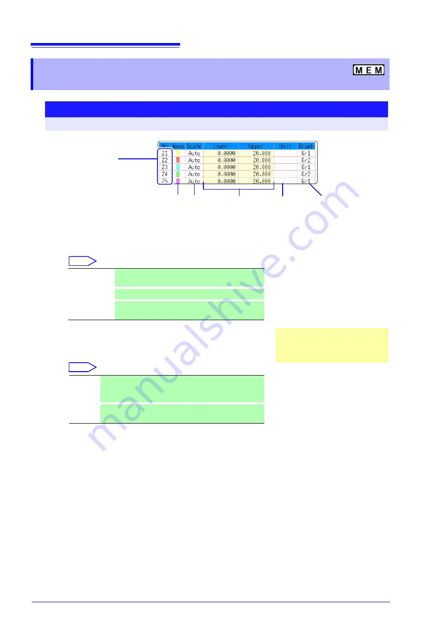
Enable waveform display, and display color
Move the cursor to the
[Wave]
column.
Select
2
Select a method to set scaling
Move the cursor to the
[Scale]
column for the Calculation No. to be set.
Select
3
Set the upper and lower limits of the display range (when
[Manual]
is selected)
Select
[Lower]
and
[Upper]
.
Select an entry method and enter the limit values.
Entry range: -9.9999E+29 to +9.9999E+29
See:
4
Specify the physical units
Move the cursor to the
[Unit]
column.
Select an entry method and enter the physical units.
See:
5
Select the graph to be displayed.
(When split screen (
[Format]
item on the
[Status]
sheet) is
[Dual]
or higher)
Move the cursor to the
[Graph]
column and select the graph number.
Waveform
color
Upper and
lower limits
Displayed
measurement
units
Display
range set-
ting method
Calculation No.
To copy settings
between Calculation Nos.:
Select F1 [Copy].
1 2
4
3
Graph to display
6
1
On-Off
Set On to display the waveform of the flashing cursor
column (default setting). Set to Off to hide display.
2
↑↓
Select the waveform color.
3
All On-Off
Select On to display all waveforms. Select Off to hide all
waveforms.
1
Auto
Automatically sets the display range of the vertical axis. (After
calculation, the upper and lower limits are obtained from the
results, and set automatically.)
2
Manual
Upper and lower limits of the vertical axis display range are
entered manually.
Depending on calculation results, auto-
matic scaling settings may be unsatisfac-
tory, in which case the limits must be
entered manually.
Summary of Contents for 8847
Page 1: ...MEMORY HiCORDER Instruction Manual 8847 December 2010 Revised edition 4 8847A981 04 10 12H ...
Page 2: ......
Page 18: ...Operating Precautions 8 ...
Page 26: ...1 4 Basic Key Operations 16 ...
Page 74: ...4 4 Waveform Observation 64 ...
Page 98: ...5 5 Managing Files 88 ...
Page 110: ...6 6 Miscellaneous Printing Functions 100 ...
Page 126: ...7 8 Seeing Block Waveforms 116 ...
Page 160: ...8 10 Making Detailed Settings for Input Modules 150 ...
Page 198: ...10 6 Numerical Calculation Type and Description 188 ...
Page 296: ...15 7 Controlling the Instrument with Command Communications LAN USB 286 ...
Page 304: ...16 2 External I O 294 ...
Page 362: ...Appendix 5 FFT Definitions A28 ...
Page 368: ...Index Index 6 ...
Page 369: ......
Page 370: ......
Page 371: ......


