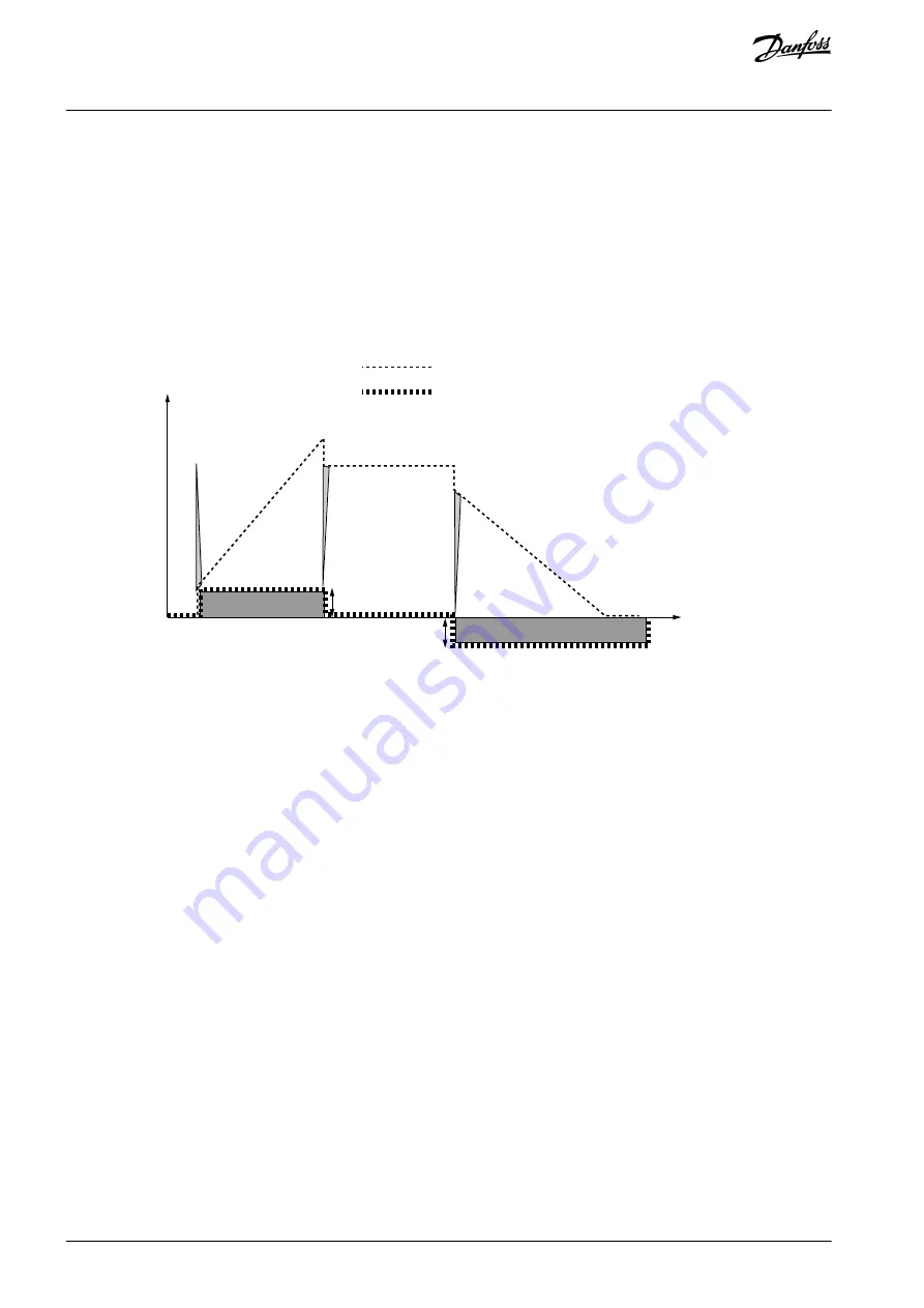
P2.1.13, I-time = 1.00 s
P2.1.14, D-time = 1.00 s
Minimum frequency = 0 Hz
Error value (setpoint – process value) = ±10%
Maximum frequency = 50 Hz
As the power is switched on, the system detects the difference between the setpoint and the actual process value and starts to
either raise or decrease (in case the error value is negative) the PID output according to the I-time. Once the difference between the
setpoint and the process value has been reduced to 0, the output is reduced by the amount corresponding to the value of parame-
ter
P2.1.13
.
In case the error value is negative, the AC drive reacts reducing the output correspondingly.
Hz
t
PID output
Error value
D-part
I-p
ar
t
I-pa
rt
D-part
P-part=5 Hz
Error=10%
D-part
P-part= -5 Hz
Error= -10%
e
3
0
b
h
0
2
6
.1
0
Illustration 29: PID Output Curve with the Values of Example 2
Example 3
Given values:
P2.1.12, P = 100%
P2.1.13, I-time = 0.00 s
P2.1.14, D-time = 1.00 s
Minimum frequency = 0 Hz
Error value (setpoint – process value) = ±10%/s
Maximum frequency = 50 Hz
As the error value increases, also the PID output increases according to the set values (Dtime = 1.00 s).
AB296635287482en-000301 / DPD00903
176 | Danfoss A/S © 2023.02
Parameter Descriptions
VACON® NX All-in-One
Application Guide
Summary of Contents for VACON NX
Page 1: ...Application Guide VACON NX All in One drives danfoss com...
Page 2: ......


