


Configuration – 4
4–47
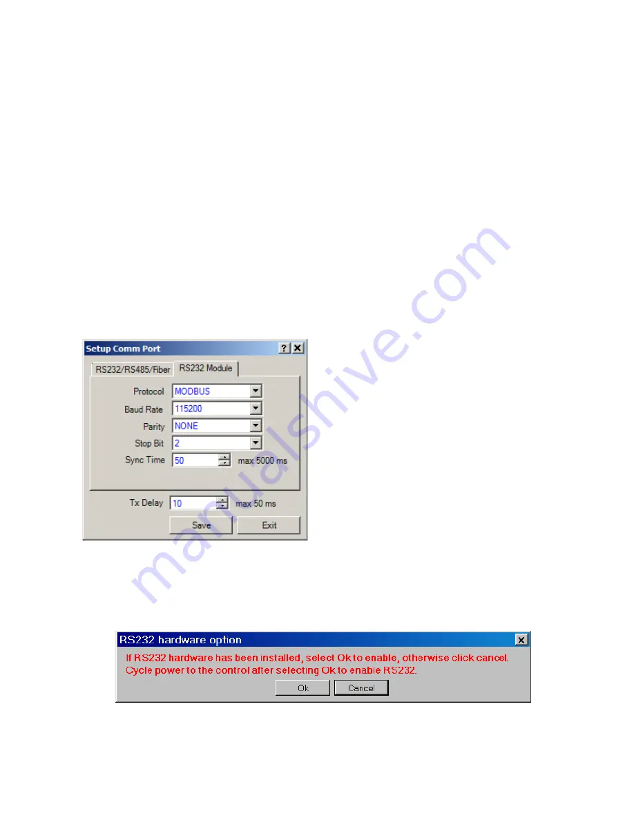
RS-232 Port Module Setup From CapTalk
®
To setup the RS-232 Port from CapTalk proceed
as follows:
1. Select
Communication/Setup/Comm
Port
from the CapTalk toolbar. CapTalk
will display the "Setup Comm Port"
dialog screen (Figure 4-28).
2.
Select the RS232 Module tab.
Depending on the status of the RS-232
option in the control, CapTalk will
respond as follows:
• If the RS-232 option is disabled
in the control, CapTalk will display
the RS-232 Hardware option dialog
screen (Figure 4-33).
• If the RS-232 option is enabled in
the control, CapTalk will display the
Setup RS-232 Comm Port dialog
screen (Figure 4-32).
Figure 4-32 Setup RS-232 Comm Port
Dialog Screen
3.
If the RS-232 Hardware option dialog
screen (Figure 4-33) is displayed, then
proceed as follows:
a. If the RS-232 hardware is present,
select "OK" to enable. CapTalk will
then display the Setup RS-232
Comm Port dialog screen (Figure
4-32). Go to Step 4.
b. If the RS-232 hardware is not
present, select "Cancel". CapTalk
will return to the Main screen.
4. Enter the desired settings for the
following parameters:
• Protocol
• Baud Rate
• Parity
• Stop Bits
• Sync Time
• TX Delay
5.
Select "Save". CapTalk will display a
"Confirm Writing to Device" confirmation
screen (Figure 4-2).
6.
Select "OK". CapTalk will display a
"Setpoints Successfully Written to
Control" confirmation screen (Figure
4-14).
7.
Verify that removing power to the control
will not cause upset operation conditions
on the control.
8.
Remove power to the control, and then
reapply power to the control.
9.
If DNP3.0 was selected in Step 4 and
Source Address Validation is desired,
then see "Enabling Source Address
Validation" later in this section.
The RS-232 option for the control is now enabled.
See
Communication Using Serial Port section of
Chapter 3 to connect to the target control through
the RS-232 connection.
Figure 4-33
RS-232 Comm Port Option Dialog Screen
Summary of Contents for M-6280A
Page 1: ...Instruction Book M 6280A Digital Capacitor Bank Control ...
Page 33: ...This Page Left Intentionally Blank ...
Page 53: ...xx M 6280A Instruction Book This Page Left Intentionally Blank ...
Page 56: ...Introduction 1 1 3 Figure 1 1 Functional Diagram ...
Page 59: ...1 6 M 6280A Instruction Book This Page Left Intentionally Blank ...
Page 66: ...2 7 Operation 2 Figure 2 1 M 6280A Front Panel ...
Page 137: ...3 14 M 6280A Instruction Book Figure 3 13 CapTalk Main Screen Connected Mode ...
Page 172: ...3 49 CapTalk 3 Figure 3 67 CBEMA Settings Dialog Screen ...
Page 179: ...3 56 M 6280A Instruction Book Figure 3 87 M 6280A DNP Configurator Dialog Screen ...
Page 184: ...3 61 CapTalk 3 Figure 3 98 CapPlot Window with Data Logging Data Example ...
Page 185: ...3 62 M 6280A Instruction Book Figure 3 99 CapPlot Window with Oscillograph Data Example ...
Page 191: ...3 68 M 6280A Instruction Book This Page Left Intentionally Blank ...
Page 313: ...M 6280A Instruction Book 4 122 Figure 4 63 Setpoints Dialog Screen VAr Control ...
Page 314: ...Configuration 4 4 123 Figure 4 64 Setpoints Dialog Screen Current Control ...
Page 451: ...D 4 M 6280 Instruction Book This Page Left Intentionally Blank ...


