


Configuration – 4
4–27
For example: control D1 on Feeder F4 in substation
S2 will have the following.
1. Individual not duplicated device
address (0x212)
2.
Feeder address = 0x4003
3.
Substation address = 0x5001
In order to poll D1 on an individual basis address,
0x212 is used.
To invoke for example, voltage reduction individually
on D1, use direct operate with or without
acknowledge for address 0x212 on the appropriate
point.
To invoke voltage reduction on Feeder F4, use direct
operate without acknowledge to address 0x4003
instead of 3 different commands sent to D1, D2
and D3 individually.
Similarly, invoking voltage reduction on an entire
substation requires a direct operate command
without acknowledge to be sent to that substation
address e.g. substation S2 ( address 0x5001).
NOTE: The same concept applies to network
configuration (Figure 4-25).
Feeder and/or Substation Addressing
Each control has three addresses.
1.
Device address
2.
Feeder address
3.
Substation address
Any valid DNP command (Figure 4-24) can be
used to communicate with individual controls
using the "Device" address. To address a
group of controls using the "Feeder" and/or the
"Substation" addresses, a DNP command with
no acknowledgment shall be used. For example
Direct Operate with NO acknowledgment (FC 06).
If a command with acknowledgment is sent by the
Client, the control will accept the command and will
reply with an acknowledgment. Since the command
was sent to multiple units, network congestion can
occur.
All addresses range from 0 to 0xFFEF. For feeder
and substation addresses, setting the value to zero
effectively "Disables"
the corresponding address. It
is important that there are no duplicate addresses
on any device on the network.
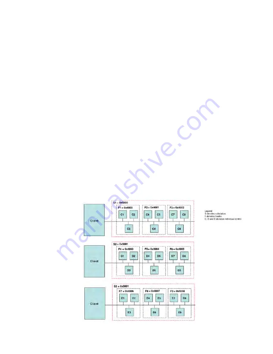
In the system depicted in Figure 4-24, there are
three substations: S1, S2, and S3. There are a total
of 9 feeders, F1-F9, grouped as shown. Each feeder
has 3 controls, one for each phase. Each control
will have 3 addresses assigned to it.
Figure 4-24 Multiple Client, Feeder and/or Substation Addressing
Summary of Contents for M-6280A
Page 1: ...Instruction Book M 6280A Digital Capacitor Bank Control ...
Page 33: ...This Page Left Intentionally Blank ...
Page 53: ...xx M 6280A Instruction Book This Page Left Intentionally Blank ...
Page 56: ...Introduction 1 1 3 Figure 1 1 Functional Diagram ...
Page 59: ...1 6 M 6280A Instruction Book This Page Left Intentionally Blank ...
Page 66: ...2 7 Operation 2 Figure 2 1 M 6280A Front Panel ...
Page 137: ...3 14 M 6280A Instruction Book Figure 3 13 CapTalk Main Screen Connected Mode ...
Page 172: ...3 49 CapTalk 3 Figure 3 67 CBEMA Settings Dialog Screen ...
Page 179: ...3 56 M 6280A Instruction Book Figure 3 87 M 6280A DNP Configurator Dialog Screen ...
Page 184: ...3 61 CapTalk 3 Figure 3 98 CapPlot Window with Data Logging Data Example ...
Page 185: ...3 62 M 6280A Instruction Book Figure 3 99 CapPlot Window with Oscillograph Data Example ...
Page 191: ...3 68 M 6280A Instruction Book This Page Left Intentionally Blank ...
Page 313: ...M 6280A Instruction Book 4 122 Figure 4 63 Setpoints Dialog Screen VAr Control ...
Page 314: ...Configuration 4 4 123 Figure 4 64 Setpoints Dialog Screen Current Control ...
Page 451: ...D 4 M 6280 Instruction Book This Page Left Intentionally Blank ...


