


3–6
M‑6280A Instruction Book
3.5
Fiber Optic Communications
The fiber optic interface is connected to the rear COM
Port of the device. It can be enabled through the front
panel under the Comm setting menu. When fiber
optic is selected, the RS-485 is disabled. The fiber
optic baud rate is selectable from 300 to 115200 bps.
The echoing of the received data is supported by
the hardware. The fiber repeat switch is located
to the right of the TX fiber transmitter connector.
Placing the switch toward the back cover turns on
Fiber Repeat (sometimes called Echo Repeat or
Echo ON) and placing it towards the front panel
disables it. Echo ON is primarily used if the control
is in a daisy chain network. Disabling the echo
transmission is usually done when there is peer to
peer communication. If the client software supports
echo canceling, as it is the case for CapTalk
®
, then
there is no need to disable echo transmission. In this
case echo cancel should be enabled on the client
software. Physical specification:
• Fiber type: Multimode
• Tested with fiber size 62.5/125
To use CapTalk to interrogate, set, or monitor the
M-6280A Digital Capacitor Bank Control using a
Fiber Optic connection the following conditions
must be met:
• The control is physically connected to a
Fiber Optic network consistent with the
hardware and connection requirements
of Section 5.1,
Communication Ports.
• CapTalk software communication
parameters and device parameters must
match the control’s default Fiber Optic
settings and the selected/default device
parameters.
Elements of the control’s Fiber Optic Port
communication parameters include the following
(default settings):
• Baud Rate (115200 bps)
• Sync Time (2 mS)
• Parity (None)
• Stop Bits (1)
Default device parameters that are at the default
settings or have been configured locally at the
control include (default settings):
• Device (Comm) Address (1)
• Protocol (MODBUS)
• Echo Cancel (fiber optic) (None)
Communication Using Fiber Optic Connection
1.
Ensure the following conditions exist:
• The control is physically connected
to the Fiber Optic network
• CapTalk is installed on the host
computer
• The control is energized
2.
Start the CapTalk program. CapTalk will
display the CapTalk "Main" dialog screen
(Figure 3‑11).
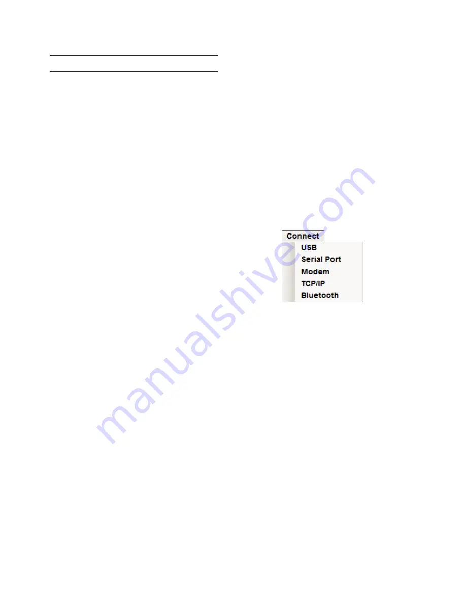
3. Select "Connect/Serial Port" from the
"Connect" drop-down menu.
CapTalk will display the Serial Port dialog
screen (Figure 3‑15).
4. Ensure that the correct COM port is
displayed.
5.
Ensure that both the Device and Comm
settings are consistent with the control’s
default values.
6.
Select "Connect". CapTalk will attempt
to connect to the target control.
7.
If CapTalk returns a "Failed to Connect"
error screen (Figure 3‑3), then perform
Steps 4, 5 and 6.
8. If Level Access is not active, then
CapTalk will display the "Successfully
Connected" dialog screen. Access is
set to Read Only" (Figure 3‑4) and
then CapTalk will display the connected
version of the CapTalk Main Screen
(Figure 3‑13).
9.
If Level Access is active and the proper
access code was entered, then CapTalk
will display the connected version of the
CapTalk Main Screen (Figure 3‑13) with
the appropriate Access Level.
Summary of Contents for M-6280A
Page 1: ...Instruction Book M 6280A Digital Capacitor Bank Control ...
Page 33: ...This Page Left Intentionally Blank ...
Page 53: ...xx M 6280A Instruction Book This Page Left Intentionally Blank ...
Page 56: ...Introduction 1 1 3 Figure 1 1 Functional Diagram ...
Page 59: ...1 6 M 6280A Instruction Book This Page Left Intentionally Blank ...
Page 66: ...2 7 Operation 2 Figure 2 1 M 6280A Front Panel ...
Page 137: ...3 14 M 6280A Instruction Book Figure 3 13 CapTalk Main Screen Connected Mode ...
Page 172: ...3 49 CapTalk 3 Figure 3 67 CBEMA Settings Dialog Screen ...
Page 179: ...3 56 M 6280A Instruction Book Figure 3 87 M 6280A DNP Configurator Dialog Screen ...
Page 184: ...3 61 CapTalk 3 Figure 3 98 CapPlot Window with Data Logging Data Example ...
Page 185: ...3 62 M 6280A Instruction Book Figure 3 99 CapPlot Window with Oscillograph Data Example ...
Page 191: ...3 68 M 6280A Instruction Book This Page Left Intentionally Blank ...
Page 313: ...M 6280A Instruction Book 4 122 Figure 4 63 Setpoints Dialog Screen VAr Control ...
Page 314: ...Configuration 4 4 123 Figure 4 64 Setpoints Dialog Screen Current Control ...
Page 451: ...D 4 M 6280 Instruction Book This Page Left Intentionally Blank ...


