


3–16
M‑6280A Instruction Book
Connect and Communication
The
Connect drop down menu is displayed when
the unit is not connected to a control. This menu
provides the user with access to the screens that
are necessary to set CapTalk
®
communication
parameters and connect to the target control. Menu
selections include
USB, Serial Port, MODEM, and
TCP/IP, and Bluetooth
®
.
USB
The USB menu selection initiates the USB dialog
screen to connect to the M‑6280A USB Port (Figure
3‑2). The user is prompted to input the required
Device and Access code. The USB/CommPort
selection identifies the computer Comm Port to be
utilized for communication.
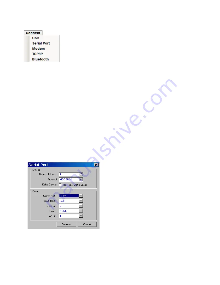
Serial Port
The
Serial Port menu selection initiates the Serial
Port
dialog screen (Figure 3‑15). The user is
prompted to input the necessary communications
information to open Serial communications through
the selected CommPort.
Figure 3‑15 Serial Port Connection
Dialog Screen
Modem
The Modem menu selection initiates the Modem
communication dialog screen (Figure 3‑16). This
screen contains the Device, Phone, PC Comm
Port and Modem parameters that are necessary
to setup and communicate with a modem attached
to the host computer and the target M-6280A. This
screen also contains a phone book, selection of
Comm Port or modem and a selection for bringing
up a terminal window after dialing.
TCP/IP
The TCP/IP menu selection initiates the TCP/IP
communication dialog screen (Figure 3‑17). This
screen contains the parameter settings for
communicating with a M-6280A over a network. The
dialog screen also includes provision for adding,
removing, saving, importing, and exporting Address
Book IP addresses.
Optional Bluetooth: The optional Bluetooth
®
(V2.0
+EDR Class 1 Type) provides wireless access to the
M-6280A. With Bluetooth the user is able to
configure the control, read status and metering
values as well as change setpoints. This option can
be field installed. There are two modes of operation
for the Bluetooth:
Mode 0 – The device is discoverable and
connectable to any client station.
Mode 1 – This mode makes the Bluetooth device
in this unit non-discoverable. A computer can only
connect to the control in this mode if the user knows
the Bluetooth device address of the unit indicated
under “
Control BT Device” in the HMI. The user
must also use a SENA Parani SD1000U USB to
Bluetooth adapter. CapTalk will communicate with
the SD1000U (see Figure 3‑18) when using the
Non-discoverable Bluetooth dialog screen and
initiate communications with a control.
NOTE
: When using the Parani SD1000U, no
user setup of the device is required,
and the utility provided with the device
is not needed. CapTalk will communicate
directly with the SD1000U when using
the Figure 3-18 dialog screen without
the need to configure it.
Mode 1 has been added to meet CIP requirement.
(CIP‑0007‑4 System Security Management) (R2.3)
Summary of Contents for M-6280A
Page 1: ...Instruction Book M 6280A Digital Capacitor Bank Control ...
Page 33: ...This Page Left Intentionally Blank ...
Page 53: ...xx M 6280A Instruction Book This Page Left Intentionally Blank ...
Page 56: ...Introduction 1 1 3 Figure 1 1 Functional Diagram ...
Page 59: ...1 6 M 6280A Instruction Book This Page Left Intentionally Blank ...
Page 66: ...2 7 Operation 2 Figure 2 1 M 6280A Front Panel ...
Page 137: ...3 14 M 6280A Instruction Book Figure 3 13 CapTalk Main Screen Connected Mode ...
Page 172: ...3 49 CapTalk 3 Figure 3 67 CBEMA Settings Dialog Screen ...
Page 179: ...3 56 M 6280A Instruction Book Figure 3 87 M 6280A DNP Configurator Dialog Screen ...
Page 184: ...3 61 CapTalk 3 Figure 3 98 CapPlot Window with Data Logging Data Example ...
Page 185: ...3 62 M 6280A Instruction Book Figure 3 99 CapPlot Window with Oscillograph Data Example ...
Page 191: ...3 68 M 6280A Instruction Book This Page Left Intentionally Blank ...
Page 313: ...M 6280A Instruction Book 4 122 Figure 4 63 Setpoints Dialog Screen VAr Control ...
Page 314: ...Configuration 4 4 123 Figure 4 64 Setpoints Dialog Screen Current Control ...
Page 451: ...D 4 M 6280 Instruction Book This Page Left Intentionally Blank ...


