


2–55
Operation – 2
Temperature Sensor Calibration From The HMI
1. Press the "ENT" (UTIL Hot Button)
pushbutton to awaken the unit. The
menu will advance to "UTILITIES".
UTILITIES
W
COMM
MNTR
V
2.
Press the Down Arrow pushbutton once.
The unit will display the following:
Calibration/Test
W
V
3. Press the Down Arrow pushbutton as
necessary to navigate to the "Temp
Calibration" screen.
Temp Calibration
Press ENT to Proceed
4.
Press the "ENT" pushbutton. The Level
Access prompt will be displayed.
ENTER LEVEL ACCESS
_
NOTE: When entering the Level Access code
the display will automatically advance
the cursor to the next digit when input
is momentarily paused.
5.
Enter the Level Access code, then press
the "ENT" pushbutton.
If a valid Level Access code was entered,
then the display will briefly flash a
confirmation screen, then a "C". If not,
reenter a valid code.
Enter temperature
73 'F (C)
C
6. At the cursor, input the desired
Temperature value (From -40 to 185
Degrees "F" or -40 to 85 Degrees "C")
utilizing the arrow pushbuttons, then
press the "ENT" pushbutton. The display
will return to the "Temp Calibration"
screen.
Temp Calibration
Press ENT to Proceed
Temperature Sensor Calibration From
CapTalk
®
To calibrate the temperature sensor from CapTalk
perform the following:
NOTE: Temperature Metering Dialog Screen
(Figure 2-35) can be displayed at
the same time as the Temperature
Calibration Dialog Screen.
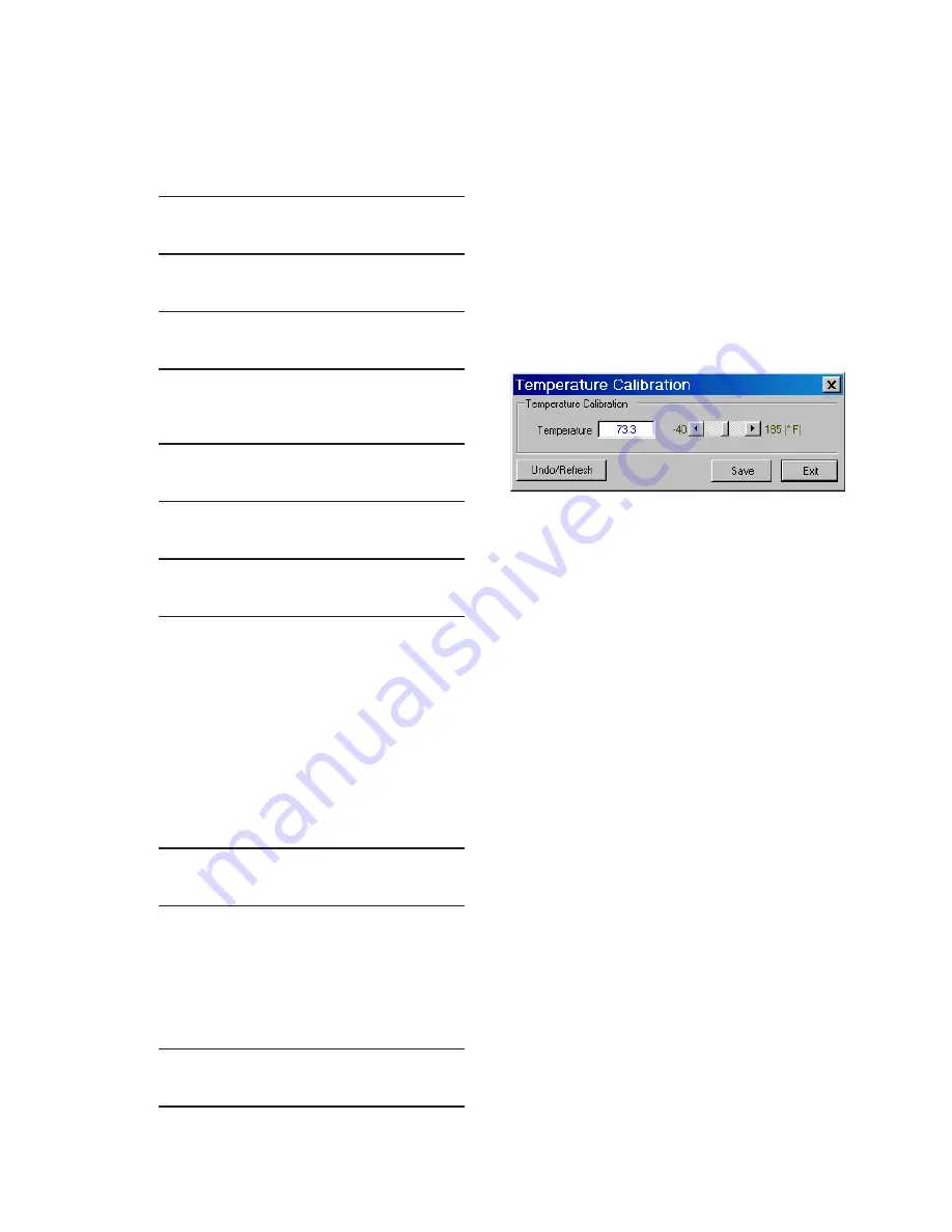
1. Select
Utility/Temperature Calibration
from the CapTalk toolbar. CapTalk will
display the "Temperature Calibration"
dialog screen Figure 2-46.
Figure 2‑46 Temperature Calibration
Dialog Screen
2. Enter the desired Temperature value
from –40 to 185 Degrees "F" or –40 to
85 Degrees "C", then select "Save".
CapTalk will display a "Setpoints
successfully written to the control"
confirmation screen Figure 2-49.
Summary of Contents for M-6280A
Page 1: ...Instruction Book M 6280A Digital Capacitor Bank Control ...
Page 33: ...This Page Left Intentionally Blank ...
Page 53: ...xx M 6280A Instruction Book This Page Left Intentionally Blank ...
Page 56: ...Introduction 1 1 3 Figure 1 1 Functional Diagram ...
Page 59: ...1 6 M 6280A Instruction Book This Page Left Intentionally Blank ...
Page 66: ...2 7 Operation 2 Figure 2 1 M 6280A Front Panel ...
Page 137: ...3 14 M 6280A Instruction Book Figure 3 13 CapTalk Main Screen Connected Mode ...
Page 172: ...3 49 CapTalk 3 Figure 3 67 CBEMA Settings Dialog Screen ...
Page 179: ...3 56 M 6280A Instruction Book Figure 3 87 M 6280A DNP Configurator Dialog Screen ...
Page 184: ...3 61 CapTalk 3 Figure 3 98 CapPlot Window with Data Logging Data Example ...
Page 185: ...3 62 M 6280A Instruction Book Figure 3 99 CapPlot Window with Oscillograph Data Example ...
Page 191: ...3 68 M 6280A Instruction Book This Page Left Intentionally Blank ...
Page 313: ...M 6280A Instruction Book 4 122 Figure 4 63 Setpoints Dialog Screen VAr Control ...
Page 314: ...Configuration 4 4 123 Figure 4 64 Setpoints Dialog Screen Current Control ...
Page 451: ...D 4 M 6280 Instruction Book This Page Left Intentionally Blank ...


