


3–54
M‑6280A Instruction Book
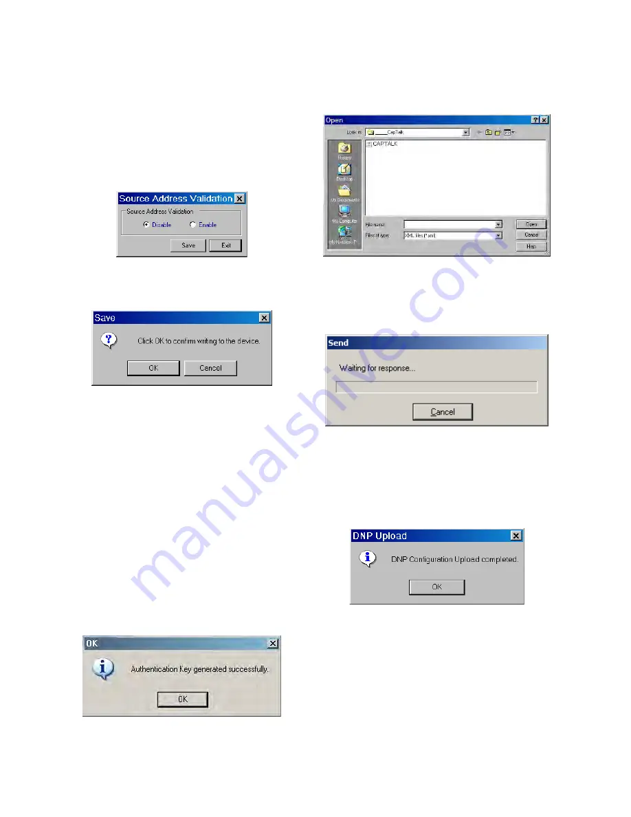
Utility/Source Address Validation
The
Source Address Validation feature is available
from the Utility menu selection. When Source
Address Validation is enabled it applies only when
DNP3.0 Protocol has been selected regardless of
the physical interface. If enabled, the client address
must match the address set by the user in the DNP
Configuration file before accepting the message as
a valid one.
Figure 3‑79 Source Address Validation
Dialog Screen
Figure 3‑80
Confirm Writing to the Device
Dialog Screen
Utility/Send DNP Configuration File
■
NOTE: When communicating using Ethernet to
a control, the DNP Configuration Utility,
Send and Receive functions are not
available in CapTalk
®
and are grayed out.
The Send DNP Configuration File menu selection
provides the user with the capability to upload a
DNP configuration file to the control. To upload a
DNP configuration file proceed as follows:
1.
From the CapTalk Main Screen select
Utility/Send DNP Configuration File.
CapTalk will display the Authentication
Key Generated dialog screen (Figure
3‑81).
Figure 3‑81 Authentication Key Generated
Dialog Screen
2. Select "OK". CapTalk will display the
Open File Dialog
screen (Figure 3‑82)
with a default *.xml file extension.
Figure 3‑82 Open File Dialog Screen
3.
Select the target file, then select "Open".
CapTalk will display the "Send" dialog
screen Figure 3-83.
Figure 3‑83 Send Dialog Screen
4.
When the DNP Configuration file has
been uploaded CapTalk will display
a confirmation screen (Figure 3‑84).
Select "OK". CapTalk will return to the
Main Screen.
Figure 3‑84 Upload Dialog Screen
Summary of Contents for M-6280A
Page 1: ...Instruction Book M 6280A Digital Capacitor Bank Control ...
Page 33: ...This Page Left Intentionally Blank ...
Page 53: ...xx M 6280A Instruction Book This Page Left Intentionally Blank ...
Page 56: ...Introduction 1 1 3 Figure 1 1 Functional Diagram ...
Page 59: ...1 6 M 6280A Instruction Book This Page Left Intentionally Blank ...
Page 66: ...2 7 Operation 2 Figure 2 1 M 6280A Front Panel ...
Page 137: ...3 14 M 6280A Instruction Book Figure 3 13 CapTalk Main Screen Connected Mode ...
Page 172: ...3 49 CapTalk 3 Figure 3 67 CBEMA Settings Dialog Screen ...
Page 179: ...3 56 M 6280A Instruction Book Figure 3 87 M 6280A DNP Configurator Dialog Screen ...
Page 184: ...3 61 CapTalk 3 Figure 3 98 CapPlot Window with Data Logging Data Example ...
Page 185: ...3 62 M 6280A Instruction Book Figure 3 99 CapPlot Window with Oscillograph Data Example ...
Page 191: ...3 68 M 6280A Instruction Book This Page Left Intentionally Blank ...
Page 313: ...M 6280A Instruction Book 4 122 Figure 4 63 Setpoints Dialog Screen VAr Control ...
Page 314: ...Configuration 4 4 123 Figure 4 64 Setpoints Dialog Screen Current Control ...
Page 451: ...D 4 M 6280 Instruction Book This Page Left Intentionally Blank ...


