


14.2 Servo control
14-37
• MD3069 digit 0 (Pn127 digit 0) SWITCH_FUNCTION_2 (For each axis) ##
Meaning:
Method for setting position loop gain
Setting value: 0 --- Drive setting value is used.
1 --- The value set from CNC cyclic data is used.
Note: Be sure to set this parameter to "1".
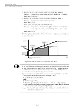
• MD3425 (Pn505) OVERFLOW_LEVEL (For each axis) ##
Meaning:
Excessive deviation area (Over flow level)
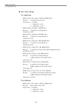
Setting value: Values obtained from the following equations are to be set.
(The number of encoder pulses is a 4-multiplication value.)
• For motor encoder
• For External encoder
Where, (PPN) = The number of External encoder pulses / Single revolution of motor.
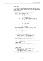
Spindle drive
• MD6522 (Cn522) MULTI_FUNCTION_SEL_SSC ##
Meaning:
Multi-function selection SSC
Setting value: 0 --- SSC is set to "Soft start cancelled."
1 --- SSC is set to "Servo mode."
Note: Be sure to set the parameter to "1". When position control is carried
out (for example, for orientation, tapping, or others), the operation
mode must be "Full-time Servo mode."
• MD6837 (Cn831) GAIN_SWITCH ##
Meaning:
Method for setting position loop gain (Variable KP selection)
Setting value: 0000 --- Drive setting value is used.
0100 --- A value obtained from CNC cyclic data is used.
Note: Be sure to set the parameter to "0100".
• MD6965 (Cn8B1) OVERFLOW_LEVEL (For each axis) ##
Meaning:
Excessive deviation area (Over flow level)
Setting value: Values obtained from the following equations are to be set. (The number
of encoder pulses is a 4-multiplication value.)
• For pulse encoder
• For serial encoder
The number of revolutions [min
-1
] at maximum feed speed
×
The number of motor encoder pulses
×
1.2
Position loop gain [1/s]
×
256
×
60
The number of revolutions [min
-1
] at maximum feed speed
×
(PPN)
×
1.2
Position loop gain [1/s]
×
256
×
60
The number of revolutions [min
-1
] at maximum feed speed
×
The number of motor encoder pulses
×
1.2
Position loop gain [1/s]
×
60
The number of revolutions [min
-1
] at maximum feed speed
×
The number of motor encoder pulses
×
1.2
Position loop gain [1/s]
×
256
×
60
Содержание CNC Series
Страница 1: ...Maintenance Manual Serviceman Handbook MANUAL No NCSIE SP02 19 Yaskawa Siemens CNC Series...
Страница 26: ...Part 1 Hardware...
Страница 38: ...System Configuration 1 2 3 Spindle motor designations 1 12...
Страница 58: ...Installing the control panels 2 3 5 Installing lightning surge absorbers 2 20...
Страница 62: ...Installing the motors 3 4...
Страница 84: ...Connection method 4 3 2 Setting the rotary switches on the inverters and servo units 4 22...
Страница 96: ...Part 2 Software...
Страница 102: ...Software configuration 6 6...
Страница 103: ...7 1 Chapter 7 Backup 7 1 How to archive 7 2 7 2 Network settings 7 7 7 2 1 YS 840DI settings 7 7 7 2 2 PC settings 7 14...
Страница 105: ...7 1 How to archive 7 3 3 Select the Workpieces folder 4 Click on Archive File which is one of the right side keys...
Страница 113: ...7 2 Network settings 7 11 8 Click on the radio button to the left of Specify an IP address...
Страница 121: ...7 2 Network settings 7 19...
Страница 122: ...Part 3 PLC...
Страница 154: ...Part 4 Setting up and maintenance...
Страница 160: ...Overview of System 10 1 2 Basic operation 10 6...
Страница 204: ...How to use Digital Operation 12 2 9 Setting the password setting for write prohibit 12 32...
Страница 327: ...Error and Troubleshooting 15 4...
Страница 328: ...15 1 Errors without Alarm Display and Troubleshooting 15 5...
Страница 329: ...Error and Troubleshooting 15 6...
Страница 343: ...Maintenance and Check 16 3 3 Setting up Initializing Absolute encoder 16 14...


