


Maintenance and Check
16.2.4 Periodical check
16-6
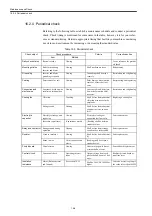
16.2.4 Periodical check
Referring to the following table, establish a maintenance schedule and conduct a periodical
check. Check timing is mentioned for some items in the table; however, it is for your refer-
ence as standard timing. Determin appropriate timing that best fits your machine considering
use status and environment by increasing or decreasing the standard value.
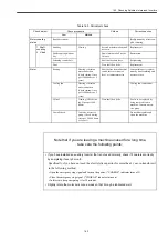
Table 16.5 Periodical check
Check object
Check procedure
Criteria
Corrective action
Item
Method
Daily check status
Review records
Viewing
Use as reference for periodi-
cal check.
Mounting status
Bolts for mounting
Inverter and Motor
Viewing
Shall not become loose.
Retightening
Grounding
Inverter and Motor
grounding terminals
Viewing
Grounding shall be made
securely.
Restoration and retightening
Coating
Paint removal or rust
Viewing
Paint damage, discoloration,
removal, or rust shall not
exist.
Rustproofing and repainting
Connection and
electric wire
Looseness, break on wire
insulation, terminal box
Viewing
Looseness, break, deteriora-
tion, or deformation shall
not exist.
Restoration and retightening
Cooling fan
Vibration
Touching
Shall be free from abnormal
vibration or increase in the
amplitude.
Replacing a cooling fan
Strange sound
Hearing
Shall be free from abnormal
sound or increase in noise
level.
Electrolytic
capacitor
Electrolyte leakage and
expansion
Viewing
Electrolyte leakage or
expansion shall not exist.
Parts replacement
(Measure capacitance)
(Capacitance meter)
(Reading shall be within a
standard value.)
Relay and contactor
Strange sound during
operation
Hearing
Shall be free from strange
sound such as rattle sound.
Parts replacement
Resistor
Crack in insulator
Viewing
Shall be free from abnormal-
ity
Parts replacement
Break in wire
Circuit analyzer and
others
Reading shall be within a
standard value.
Printed board
Discoloration
Viewing
Abnormal or partial discol-
oration shall not exist.
Printed board replacement
Control circuit
Functional check
Operating inverter
alone
Output voltage from each
phase shall no be out of bal-
ance.
Readjust printed board or
repair inverter.
Insulation
resistance
Motor (Between stator
and Ground)
See section 16.2.3
Shall be 500 VDC 10M
Ω
or
higher.
Contact our service group if
the value is less than 10M
Ω
Содержание CNC Series
Страница 1: ...Maintenance Manual Serviceman Handbook MANUAL No NCSIE SP02 19 Yaskawa Siemens CNC Series...
Страница 26: ...Part 1 Hardware...
Страница 38: ...System Configuration 1 2 3 Spindle motor designations 1 12...
Страница 58: ...Installing the control panels 2 3 5 Installing lightning surge absorbers 2 20...
Страница 62: ...Installing the motors 3 4...
Страница 84: ...Connection method 4 3 2 Setting the rotary switches on the inverters and servo units 4 22...
Страница 96: ...Part 2 Software...
Страница 102: ...Software configuration 6 6...
Страница 103: ...7 1 Chapter 7 Backup 7 1 How to archive 7 2 7 2 Network settings 7 7 7 2 1 YS 840DI settings 7 7 7 2 2 PC settings 7 14...
Страница 105: ...7 1 How to archive 7 3 3 Select the Workpieces folder 4 Click on Archive File which is one of the right side keys...
Страница 113: ...7 2 Network settings 7 11 8 Click on the radio button to the left of Specify an IP address...
Страница 121: ...7 2 Network settings 7 19...
Страница 122: ...Part 3 PLC...
Страница 154: ...Part 4 Setting up and maintenance...
Страница 160: ...Overview of System 10 1 2 Basic operation 10 6...
Страница 204: ...How to use Digital Operation 12 2 9 Setting the password setting for write prohibit 12 32...
Страница 327: ...Error and Troubleshooting 15 4...
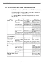
Страница 328: ...15 1 Errors without Alarm Display and Troubleshooting 15 5...
Страница 329: ...Error and Troubleshooting 15 6...
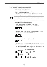
Страница 343: ...Maintenance and Check 16 3 3 Setting up Initializing Absolute encoder 16 14...


