


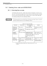


16.2 Checking Spindle motors and Invertors
16-5
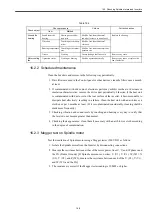
16.2.2 Scheduled maintenance
Clean the Inverters and motors in the following way periodically.
1. If air filters are used in the Control panel or other devices, clean the filters once a month
at least.
2. If contaminated with dirt or dust, electronic parts may exhibit overheat or decrease in
insulation characteristics; remove the dirt or dust periodically. Likewise, if the heat sink
is contaminated with dust or oil at the rear surface of the inverter, it becomes unable to
dissipate heat effectively, resulting in a failure. Clean the heat sink with an air blow or a
cloth once per 6 months at least. (If it is contaminated considerably, cleaning shall be
made more frequently.)
3. Checking vibration and sound levels by touching and hearing every day to verify that
the levels do not become greater than normal.
4. Checking their appearance, clean them if necessary with an air blow or cloth according
to the degree of contamination.
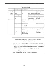
16.2.3 Megger test on Spindle motor
Test the insulation of Spindle motor using a Megger tester (500 VDC) as follows:
1. Isolate the Spindle motor from the Inverter by disconnecting connections.
2. Measure the resistance between either of the motor power lines U, V, and W phases and
the FG (Frame Ground). [If Spindle motor uses 6 wires: U (U1), V (V1), W (W1), X
(U2), Y (V2), and Z (W2); measure the resistance between each of the U (U1), V (V1),
and W (W1) and the FG.]
3. The resistance is correct if the Megger tester reading is 10 M
Ω
or higher.
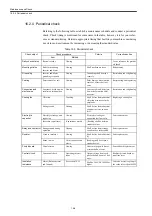
Around the
bearing
Sound from the
bearing
Hearing or ausculta-
tion stick
Shall be free from abnormal
sound or increase in noise level.
Replace the bearing.
Vibration
Touching or vibration
meter
Shall be free from abnormal
vibration
Bearing temperature Touching or thermom-
eter
Shall be free from abnormal tem-
perature rise
Grease
Viewing
Grease leakage shall not exist
Remove any cause.
Motor cooling
fan
Operation status
Viewing or hearing
Shall be operated normally
Remove any cause or replace the
fan if defective.
Table 16.4
Check object
Check procedure
Criteria
Corrective action
Item
Method
Содержание CNC Series
Страница 1: ...Maintenance Manual Serviceman Handbook MANUAL No NCSIE SP02 19 Yaskawa Siemens CNC Series...
Страница 26: ...Part 1 Hardware...
Страница 38: ...System Configuration 1 2 3 Spindle motor designations 1 12...
Страница 58: ...Installing the control panels 2 3 5 Installing lightning surge absorbers 2 20...
Страница 62: ...Installing the motors 3 4...
Страница 84: ...Connection method 4 3 2 Setting the rotary switches on the inverters and servo units 4 22...
Страница 96: ...Part 2 Software...
Страница 102: ...Software configuration 6 6...
Страница 103: ...7 1 Chapter 7 Backup 7 1 How to archive 7 2 7 2 Network settings 7 7 7 2 1 YS 840DI settings 7 7 7 2 2 PC settings 7 14...
Страница 105: ...7 1 How to archive 7 3 3 Select the Workpieces folder 4 Click on Archive File which is one of the right side keys...
Страница 113: ...7 2 Network settings 7 11 8 Click on the radio button to the left of Specify an IP address...
Страница 121: ...7 2 Network settings 7 19...
Страница 122: ...Part 3 PLC...
Страница 154: ...Part 4 Setting up and maintenance...
Страница 160: ...Overview of System 10 1 2 Basic operation 10 6...
Страница 204: ...How to use Digital Operation 12 2 9 Setting the password setting for write prohibit 12 32...
Страница 327: ...Error and Troubleshooting 15 4...
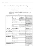
Страница 328: ...15 1 Errors without Alarm Display and Troubleshooting 15 5...
Страница 329: ...Error and Troubleshooting 15 6...
Страница 343: ...Maintenance and Check 16 3 3 Setting up Initializing Absolute encoder 16 14...


