


14.3 Motion Control
14-59
14.3.2 Acceleration/Deceleration
Feed axes
For acc./dec. of feed axes, the pre-interpolation acc./dec. typically used for rapid machining
is always enabled.
Acc./dec. control can achieve more effective acc./dec. by controlling both rate and jerk of
acc./dec. (factor for S-shaped acc./dec.).
However, for G00 feed, different rate and jerk of acc./dec. from those for maching can be
set.
For examples of machine data setting including those for rapid, precise machining, see sec-
tion 14.4.4.
Also, the post-interpolation acc./dec. (acc./dec. For each axis) can be performed in previous
ways.
For more information, see the setting method for post-interpolation acc./dec..
• MD20150 [20] GCODE_RESET_VALUES
Meaning:
Default setting of acc./dec. jerk
Setting value: 1---BRISK (jerk is disabled) is set by default.
2---SOFT (jerk is enabled) is set by default.
Standard setting value: 2
• MD20600 MAX_PATH_JERK
Meaning:
Acc./dec. jerk (acceleration rate)
Setting value: [mm/sec
3
] or [deg/sec
3
]
Note: Applied for G00 and G01.
To set acc./dec. jerk for each axis with MD32431 MAX_AX_JERK,
use a larger value (ex. 1,000,000 for initial value) for this than the
value with MD32431. If there occurs some kind of vibration, set the
20 to 50 % smaller value for this machine data than the maximum
value with MD32431.
Do not use MD32410 AX_JERK_TIME together with pre-interpola-
tion acc./dec., because the machine data is post-interpolation acc./
dec. jerk and affects machining profile errors.
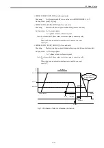
• MD20602 CURV_EFFECT_ON_PATH_ACCEL
Meaning:
Acceleration factor of curve section
By setting this machine data, the sum of tangential component and cen-
trifugal component in curve section can be calculated to meet the value
with MD32300.
Where,
• Tangential component: Decrease the acceleration speed in the curve
section as shown with MD32300
×
(1.0 - MD20602).
• Centrifugal component: Decrease the speed at the corner of curve sec-
tion as shown with MD32431
×
MD20603.
Setting value: 0 to 1.0
Standard setting value: 0.75
Содержание CNC Series
Страница 1: ...Maintenance Manual Serviceman Handbook MANUAL No NCSIE SP02 19 Yaskawa Siemens CNC Series...
Страница 26: ...Part 1 Hardware...
Страница 38: ...System Configuration 1 2 3 Spindle motor designations 1 12...
Страница 58: ...Installing the control panels 2 3 5 Installing lightning surge absorbers 2 20...
Страница 62: ...Installing the motors 3 4...
Страница 84: ...Connection method 4 3 2 Setting the rotary switches on the inverters and servo units 4 22...
Страница 96: ...Part 2 Software...
Страница 102: ...Software configuration 6 6...
Страница 103: ...7 1 Chapter 7 Backup 7 1 How to archive 7 2 7 2 Network settings 7 7 7 2 1 YS 840DI settings 7 7 7 2 2 PC settings 7 14...
Страница 105: ...7 1 How to archive 7 3 3 Select the Workpieces folder 4 Click on Archive File which is one of the right side keys...
Страница 113: ...7 2 Network settings 7 11 8 Click on the radio button to the left of Specify an IP address...
Страница 121: ...7 2 Network settings 7 19...
Страница 122: ...Part 3 PLC...
Страница 154: ...Part 4 Setting up and maintenance...
Страница 160: ...Overview of System 10 1 2 Basic operation 10 6...
Страница 204: ...How to use Digital Operation 12 2 9 Setting the password setting for write prohibit 12 32...
Страница 327: ...Error and Troubleshooting 15 4...
Страница 328: ...15 1 Errors without Alarm Display and Troubleshooting 15 5...
Страница 329: ...Error and Troubleshooting 15 6...
Страница 343: ...Maintenance and Check 16 3 3 Setting up Initializing Absolute encoder 16 14...


