


14.1 Fundamental settings
14-9
Setting switches and others at drives
Setting Converter station numbers
The station number of the Converter PROFIBUS is set to 6 by factory default.
In case multiple Converters are to be connected, you need to assign a unique station number
to each Converter.
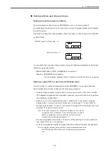
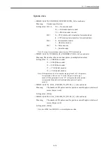
If you want to change the station numbers of the Converters, set the Converter switch (SW1)
as shown below.
You can check the Converter station numbers using the following parameters on the bottom
of the drive parameter screen.
• MD918 PROFIBUS_NODE_ADDRESS (For each axis)
Meaning: PROFIBUS station number
A station number is displayed for a Converter to which the drive is connected.
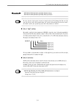
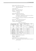
Setting a rotary SW for each Servo/Spindle drive
A rotary switch, for setting slot information of the PROFIBUS, is associated with each
Servo/Spindle drive. Set the switches in the following procedures:
• Assign an integer number, starting with 0, in succession to each of the rotary switches.
(The numbers assigned must be sequential; otherwise, you need to take care in perform-
ing a hardware configuration.)
• In the case of a 2-axis-combined Servo drive, numbers for 2 axes must be assigned
although only 1 rotary switch exists. In this case, if you assign "2" to the switch for
example, both numbers "2" and "3" will actually be assigned. For this reason, you need
to assign "4" to the next rotary switch.
Note: You need to configure axes so that even numbers (0, 2, 4) may be
assigned to rotary switches for 2-axis-combined drives. If an odd
number is assigned to a rotary switch, the switch is treated as
assigned with a predetermined number "-1".
• You can assign numbers 0-6 under 1 Converter. (If the end edge is a 2-axis-combined
type, numbers 0-5 are to be assigned.)
As far as no duplicated number is assigned, the drives need not be placed sequentially.
Note: In case any incorrect setting is made, Converter communication mod-
ule LED lights up in Red; otherwise, it lights up in green in normal
case.
Default value: 1st Converter --- 6
2nd Converter --- 7
:
1
ON
OFF
2 3 4 5 6 7 8
1 2 3 4 5 6 7 8
ON
OFF
Содержание CNC Series
Страница 1: ...Maintenance Manual Serviceman Handbook MANUAL No NCSIE SP02 19 Yaskawa Siemens CNC Series...
Страница 26: ...Part 1 Hardware...
Страница 38: ...System Configuration 1 2 3 Spindle motor designations 1 12...
Страница 58: ...Installing the control panels 2 3 5 Installing lightning surge absorbers 2 20...
Страница 62: ...Installing the motors 3 4...
Страница 84: ...Connection method 4 3 2 Setting the rotary switches on the inverters and servo units 4 22...
Страница 96: ...Part 2 Software...
Страница 102: ...Software configuration 6 6...
Страница 103: ...7 1 Chapter 7 Backup 7 1 How to archive 7 2 7 2 Network settings 7 7 7 2 1 YS 840DI settings 7 7 7 2 2 PC settings 7 14...
Страница 105: ...7 1 How to archive 7 3 3 Select the Workpieces folder 4 Click on Archive File which is one of the right side keys...
Страница 113: ...7 2 Network settings 7 11 8 Click on the radio button to the left of Specify an IP address...
Страница 121: ...7 2 Network settings 7 19...
Страница 122: ...Part 3 PLC...
Страница 154: ...Part 4 Setting up and maintenance...
Страница 160: ...Overview of System 10 1 2 Basic operation 10 6...
Страница 204: ...How to use Digital Operation 12 2 9 Setting the password setting for write prohibit 12 32...
Страница 327: ...Error and Troubleshooting 15 4...
Страница 328: ...15 1 Errors without Alarm Display and Troubleshooting 15 5...
Страница 329: ...Error and Troubleshooting 15 6...
Страница 343: ...Maintenance and Check 16 3 3 Setting up Initializing Absolute encoder 16 14...


