


Drive set-up procedure
14.2.7 Speed feedback compensation
14-44
14.2.7 Speed feedback compensation
You can suppress vibration and increase speed loop gain by using speed feedback compen-
sation.
The following explains about parameters for speed feedback compensation.
• MD3046 digit 1 (Pn110 digit 1) SWITCH_ONLINE_AUTO_TUNING (For each axis)
Meaning:
Selects speed feedback compensation function
Setting value: 0 --- Enabled
1 --- Disabled
Note: Pay attention to the polarity of "Enabled" and "Disabled".
• MD3047 (Pn111) SPEED_FEEDBACK_COMP_GAIN (For each axis)
Meaning:
Speed feedback compensation gain
Setting value: [%]
• MD3048 (Pn112) SPEED_FEEDBACK_DELAY_COMP (For each axis)
Meaning:
Speed feedback delay compensation
(Speed feedback compensation inertia gain)
Setting value: [%]
Note: Previous parameter "Speed feedback compensation attenuation fac-
tor" is no longer used.
Adjustment procedures
1. Check an axis to which you want to make an adjustment to disable speed feedback func-
tion (MD3046 digit 1 (Pn110 digit 1) = 1) by watching its torque waveform or others on
the analog monitor, and confirm that the axis vibrates.
2. Assign the following values to the parameters above for the axis you want to make an
adjustment.
• MD3047 = 100
• MD3048 = Setting value of MD3033 (Load inertia ratio) + 100
3. Enable speed feedback function (MD3046 digit 1 (Pn110 digit 1) = 0)
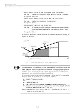
4. Adjust only the 1st-stage torque filter time constant by assigning a large value to
MD3351 (Pn401) as far as no vibration happens at any feed speed. If a vibration hap-
pens, decrease the value.
The maximum value that can be assigned to the MD3351 (Pn401) is calculated from the
speed loop gain MD3030 (Pn100) as follows. Notice that you should assign a smallest
possible value to it.
• MD3351 = 600000/(MD3030
×
2
π
)
5. If no vibration happens in the procedure 4, increase speed loop gain MD3030 (Pn100).
6. If vibration starts while you are increasing MD3030, increase MD3351 paying attention
to the above-mentioned maximum value.
Содержание CNC Series
Страница 1: ...Maintenance Manual Serviceman Handbook MANUAL No NCSIE SP02 19 Yaskawa Siemens CNC Series...
Страница 26: ...Part 1 Hardware...
Страница 38: ...System Configuration 1 2 3 Spindle motor designations 1 12...
Страница 58: ...Installing the control panels 2 3 5 Installing lightning surge absorbers 2 20...
Страница 62: ...Installing the motors 3 4...
Страница 84: ...Connection method 4 3 2 Setting the rotary switches on the inverters and servo units 4 22...
Страница 96: ...Part 2 Software...
Страница 102: ...Software configuration 6 6...
Страница 103: ...7 1 Chapter 7 Backup 7 1 How to archive 7 2 7 2 Network settings 7 7 7 2 1 YS 840DI settings 7 7 7 2 2 PC settings 7 14...
Страница 105: ...7 1 How to archive 7 3 3 Select the Workpieces folder 4 Click on Archive File which is one of the right side keys...
Страница 113: ...7 2 Network settings 7 11 8 Click on the radio button to the left of Specify an IP address...
Страница 121: ...7 2 Network settings 7 19...
Страница 122: ...Part 3 PLC...
Страница 154: ...Part 4 Setting up and maintenance...
Страница 160: ...Overview of System 10 1 2 Basic operation 10 6...
Страница 204: ...How to use Digital Operation 12 2 9 Setting the password setting for write prohibit 12 32...
Страница 327: ...Error and Troubleshooting 15 4...
Страница 328: ...15 1 Errors without Alarm Display and Troubleshooting 15 5...
Страница 329: ...Error and Troubleshooting 15 6...
Страница 343: ...Maintenance and Check 16 3 3 Setting up Initializing Absolute encoder 16 14...


