


10.2 MD components
10-5
10.2 MD components
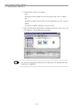
The following diagram shows the drive-related MD and the screen display types.
Schema of 840DI system
YS(840DI)
PLC (MCI board)
・
PLC application
NCK (PCU)
・
NCK application
・
CNC program analysis
・
Interpolation,
Acceleration/Deceleration
・
Position control (CNC-side processing)
・
Backlash, Pitch errors
・
Tool replacement, Data management Machine data
PROFIBUS
I/F
(MCI board)
HMI (PCU)
・
ShopMill screen
・
Standard HMI (Maintenance screen)
・
HMI application
Customer HMI (Exclusive customer screen
)
・
HMI application
Converter(MRXN)
Data bus Data bus
Data bus
Data bus
LatchSinal L
atch signal
Latch signal
Battery supply
Battery supply
Battery supply
Battery supply
Soft ware (0 0)
No parameter
Main soft ware (F0**)
Main soft ware (F***)
Main soft ware (F***)
Main soft
ware
(F***)
Main soft ware (F0**)
Main soft ware (F0**)
Parameter Cn000 1**,2**,4**,5**
Parameter
Pn000 1**,2**,3**
,4**,5**
Parameter Pn000 1**,2**,3**, 4**,5**
Parameter Pn000 1**,2**, 3**,4**,5**
The same as
the left column
The same as
the left column
General
Channel
Axis
Drive parameter
DISPLAY
-MD
Digital operator
General
Channel
MD 10000
19***
(Display screen is single)
MD 20000
29***
(Display screen is single)
Axis
MD 30000
38000
(The display screen has a page(s) per *axis.)
SP
□
X axis
□
Y axis
□
Z axis
□
B axis
□
Spindle inverter
(MXN)
Feed X axis(SGDK)
Feed Y axis
Feed Z/B axis
<1-axis drive><1-axis drive><2-axis drive><1-axis drive>
Drive parameter
(Spindle)
MD 6000 to 8999
(Servo drive)
MD 3000 to 5999
SP
□
X axis
□
Y axis
□
Z axis
□
B axis
□
・
PRM number
→
MD
numbers are changed in alignment
・
The content of setting is
also changed from decimal number (drive side) to
hexadecimal number (NC
side).
W axis
□
W axis
□
Standard setting, Function Enabled/Disabled Mode setting, Compensation Value, Max/Min. Value
setting, and Setting of Gain or Integral Time Constant for the specific function
Content of parameter
・
Mode/Function setting
・
Gain
・
Integral time constant
・
Adjustment of the axis
behavior
・
Toque level
Feed W axis
Type:JUSP-JOP02A
Monitor PRM -> (Un0**)
Function PRM -> (Fn0**)
Monitor PRM -> (Un0**) Function PRM -> (Fn0**)
Monitor PRM -> (Un0**) Function PRM -> (Fn0**)
The same as
the left column
The same as
the left column
Monitor PRM -> (Un0**) Function PRM -> (Fn0**)
Automatically set to the first address 1
Specified with even numbers
Indication/Axis-specific setting/ Content forwarding
Local bus
setting number
↓ ↓ ↓ ↓
"dr-#" indication
NC-side screen
configuration
NC-side screen configuration
"X axis" indication is defined with MD1000. The number in the " " is defined with MD20050.
Local bus setting RSW
Local bus setting RSW
Local bus setting RSW
Profibus setting is defined
through the hard ware
configuration.
Содержание CNC Series
Страница 1: ...Maintenance Manual Serviceman Handbook MANUAL No NCSIE SP02 19 Yaskawa Siemens CNC Series...
Страница 26: ...Part 1 Hardware...
Страница 38: ...System Configuration 1 2 3 Spindle motor designations 1 12...
Страница 58: ...Installing the control panels 2 3 5 Installing lightning surge absorbers 2 20...
Страница 62: ...Installing the motors 3 4...
Страница 84: ...Connection method 4 3 2 Setting the rotary switches on the inverters and servo units 4 22...
Страница 96: ...Part 2 Software...
Страница 102: ...Software configuration 6 6...
Страница 103: ...7 1 Chapter 7 Backup 7 1 How to archive 7 2 7 2 Network settings 7 7 7 2 1 YS 840DI settings 7 7 7 2 2 PC settings 7 14...
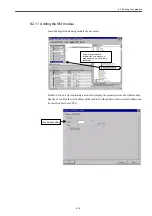
Страница 105: ...7 1 How to archive 7 3 3 Select the Workpieces folder 4 Click on Archive File which is one of the right side keys...
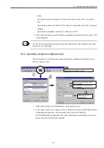
Страница 113: ...7 2 Network settings 7 11 8 Click on the radio button to the left of Specify an IP address...
Страница 121: ...7 2 Network settings 7 19...
Страница 122: ...Part 3 PLC...
Страница 154: ...Part 4 Setting up and maintenance...
Страница 160: ...Overview of System 10 1 2 Basic operation 10 6...
Страница 204: ...How to use Digital Operation 12 2 9 Setting the password setting for write prohibit 12 32...
Страница 327: ...Error and Troubleshooting 15 4...
Страница 328: ...15 1 Errors without Alarm Display and Troubleshooting 15 5...
Страница 329: ...Error and Troubleshooting 15 6...
Страница 343: ...Maintenance and Check 16 3 3 Setting up Initializing Absolute encoder 16 14...


