


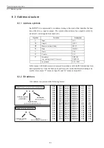


8.4 Interface structure
8-7
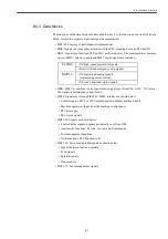
8.4.3 Data blocks
The functions of the data blocks are described below. For the function of each bit of a data
block, refer to the separate input/out signal documentation.
• DB2: PLC messages (self-diagnosis information)
• DB9: Signals sent in synchronization with the PLC scanning between PLC and NC
• DB10: Signals sent between PLC and NC as shown below. The man-machine communi-
cation (MMC) selector signals and MMC status signals are included.
• DB11: MMC or machine control panel mode signals sent from PLC to NC. NC return
the signals indicating the current mode.
• DB19: Signals sent through the PLC/MMC interface as shown below
• Control signals: MCS or WCS current position display and key disable
• Machine operation: Input from the machine control panel
• PLC messages
• PLC status signals
• DB21/22: Signals as shown below
• Control/status signals: Signals periodically sent from OB1
• Auxiliary/G functions: M code, G code, and S commands
• Tool management functions
• NCK functions: PLC function calls
• DB31-38: Servo feed/spindle signals as shown below
• Signals between feed and spindle
• Feed signals
• Spindle signals
• Drive signals
• DB71-73: Tool management signals
PLC/NC
• NC high-speed digital I/O signals
• Keyswitch and emergency stop signals
NC/PLC
• NC digital and analog signals
(representing current values)
• NC ready and other status signals.
Содержание CNC Series
Страница 1: ...Maintenance Manual Serviceman Handbook MANUAL No NCSIE SP02 19 Yaskawa Siemens CNC Series...
Страница 26: ...Part 1 Hardware...
Страница 38: ...System Configuration 1 2 3 Spindle motor designations 1 12...
Страница 58: ...Installing the control panels 2 3 5 Installing lightning surge absorbers 2 20...
Страница 62: ...Installing the motors 3 4...
Страница 84: ...Connection method 4 3 2 Setting the rotary switches on the inverters and servo units 4 22...
Страница 96: ...Part 2 Software...
Страница 102: ...Software configuration 6 6...
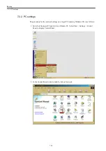
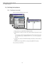
Страница 103: ...7 1 Chapter 7 Backup 7 1 How to archive 7 2 7 2 Network settings 7 7 7 2 1 YS 840DI settings 7 7 7 2 2 PC settings 7 14...
Страница 105: ...7 1 How to archive 7 3 3 Select the Workpieces folder 4 Click on Archive File which is one of the right side keys...
Страница 113: ...7 2 Network settings 7 11 8 Click on the radio button to the left of Specify an IP address...
Страница 121: ...7 2 Network settings 7 19...
Страница 122: ...Part 3 PLC...
Страница 154: ...Part 4 Setting up and maintenance...
Страница 160: ...Overview of System 10 1 2 Basic operation 10 6...
Страница 204: ...How to use Digital Operation 12 2 9 Setting the password setting for write prohibit 12 32...
Страница 327: ...Error and Troubleshooting 15 4...
Страница 328: ...15 1 Errors without Alarm Display and Troubleshooting 15 5...
Страница 329: ...Error and Troubleshooting 15 6...
Страница 343: ...Maintenance and Check 16 3 3 Setting up Initializing Absolute encoder 16 14...


