


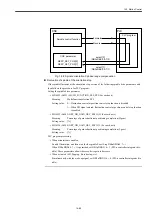


Drive set-up procedure
14.3.10 Gantry control
14-80
14.3.10 Gantry control
Apply gantry control for tandem axes. (YS 840DI master slave control is unavailable
because this function is not enabled for the drive.)
You need not adjust the setting on the drive side because CNC enables all the specific con-
trols which are different from the single-axis controls related to the gantry control.
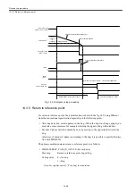
With the absolute position detection function, after the origin setting is completed, the posi-
tion deviation of the master axis and the slave axis is compensated at the same time when the
servo drive is power on and then the synchronicity deviation during traveling is checked.
With the incremental encoder, the position deviation of the master axis and the slave axis is
compensated at the same time when return to reference point is completed, and then syn-
chronicity deviation during traveling is checked.
Primary machine data related to gantry control function is listed below.
• MD37100 GANTRY_AXIS_TYPE (For each axis)
Meaning:
Gantry axis setting
1st digit: Gantry group setting (3 groups max.)
2nd digit: Master axis/slave axis
Setting value: 0---No gantry axis
1---Group 1 master axis
11---Group 1 slave axis
2---Group 2 master axis
12---Group 2 slave axis
3---Group 3 master axis
13---Group 3 slave axis
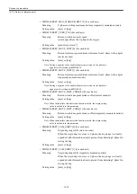
• MD37110 GANTRY_POS_TOL_WARNING (For each axis)
Meaning:
Synchronicity deviation warning output level position deviation
Setting value: [mm] or [deg]
The actual value of compensation for the position deviation of the mas-
ter axis and the slave axis is below this setting value.
• MD37120 GANTRY_POS_TOL_ERROR (For each axis)
Meaning:
Synchronicity deviation alarm output level position deviation
Setting value: [mm] or [deg]
• MD37130 GANTRY_POS_TOL_REF (For each axis)
Meaning:
When return to reference point synchronicity deviation alarm output
level position deviation
Setting value: [mm] or [deg]
Содержание CNC Series
Страница 1: ...Maintenance Manual Serviceman Handbook MANUAL No NCSIE SP02 19 Yaskawa Siemens CNC Series...
Страница 26: ...Part 1 Hardware...
Страница 38: ...System Configuration 1 2 3 Spindle motor designations 1 12...
Страница 58: ...Installing the control panels 2 3 5 Installing lightning surge absorbers 2 20...
Страница 62: ...Installing the motors 3 4...
Страница 84: ...Connection method 4 3 2 Setting the rotary switches on the inverters and servo units 4 22...
Страница 96: ...Part 2 Software...
Страница 102: ...Software configuration 6 6...
Страница 103: ...7 1 Chapter 7 Backup 7 1 How to archive 7 2 7 2 Network settings 7 7 7 2 1 YS 840DI settings 7 7 7 2 2 PC settings 7 14...
Страница 105: ...7 1 How to archive 7 3 3 Select the Workpieces folder 4 Click on Archive File which is one of the right side keys...
Страница 113: ...7 2 Network settings 7 11 8 Click on the radio button to the left of Specify an IP address...
Страница 121: ...7 2 Network settings 7 19...
Страница 122: ...Part 3 PLC...
Страница 154: ...Part 4 Setting up and maintenance...
Страница 160: ...Overview of System 10 1 2 Basic operation 10 6...
Страница 204: ...How to use Digital Operation 12 2 9 Setting the password setting for write prohibit 12 32...
Страница 327: ...Error and Troubleshooting 15 4...
Страница 328: ...15 1 Errors without Alarm Display and Troubleshooting 15 5...
Страница 329: ...Error and Troubleshooting 15 6...
Страница 343: ...Maintenance and Check 16 3 3 Setting up Initializing Absolute encoder 16 14...


