


Maintenance and Check
16.2.1 Items to be checked daily
16-4
16.2 Checking Spindle motors and Invertors
Carry out scheduled maintenance management so that the system may keep operating correctly
in good conditions.
16.2.1 Items to be checked daily
Conduct a daily check on the following items:
• To check the MRX, you must turn off the power and wait for 5 minutes before accessing inside
the unit. Be sure to wait until the "CHARGE" indicator turns off, showing the smoothing capaci-
tor has been discharged completely; otherwise, you may receive an electric shock or may be
injured.
WARNING
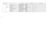
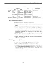
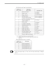
Table 16.4
Check object
Check procedure
Criteria
Corrective action
Item
Method
Environment
Ambient
temperature
Thermometer
Inverter: 0-55
℃
(Non-congelation)
Motor: 0-40
℃
Improve installation environment
so that the values may become
within normal ranges.
Humidity
hygrometer
95%RH or less
(Non-condensation)
Ventilation
Viewing
Intake/exhaust air shall flow
smoothly
Remove any obstacles blocking
smooth air flow.
Power supply
status
Voltage
Voltmeter
Shall be within a range from -15%
to +10% from rated voltage
Adjust the voltage to correct value
(by using different transformer tap
or so)
Current
Ammeter
Shall be within a rated current.
Adjust a load
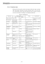
Appearance
Contamination on
Inverter, Motor, and
frame axis hole due
to dust and others
Viewing
Contamination shall not be exces-
sive than normal.
If contamination is excessive, clean
them.
Operation
status
Vibration
Touching or vibration
meter
Shall be free from abnormal
vibration or increase in the ampli-
tude.
If allowable limit is exceeded, stop
the system and remove any cause.
Bad smell
Smelling
Smell of burning is not allowed.
Stop the system and remove any
cause.
Abnormal sound
Hearing
Shall be free from abnormal
sound or increase in noise level.
If normal operation becomes diffi-
cult, stop the system and remove
any cause.
Inverter motor tem-
perature rise
Viewing or thermome-
ter.
Shall be free from abnormal tem-
perature rise.
Stop and cool the system to check if
the cooling devices such as fan
operates correctly, and make a
repair if any cause is found.
Содержание CNC Series
Страница 1: ...Maintenance Manual Serviceman Handbook MANUAL No NCSIE SP02 19 Yaskawa Siemens CNC Series...
Страница 26: ...Part 1 Hardware...
Страница 38: ...System Configuration 1 2 3 Spindle motor designations 1 12...
Страница 58: ...Installing the control panels 2 3 5 Installing lightning surge absorbers 2 20...
Страница 62: ...Installing the motors 3 4...
Страница 84: ...Connection method 4 3 2 Setting the rotary switches on the inverters and servo units 4 22...
Страница 96: ...Part 2 Software...
Страница 102: ...Software configuration 6 6...
Страница 103: ...7 1 Chapter 7 Backup 7 1 How to archive 7 2 7 2 Network settings 7 7 7 2 1 YS 840DI settings 7 7 7 2 2 PC settings 7 14...
Страница 105: ...7 1 How to archive 7 3 3 Select the Workpieces folder 4 Click on Archive File which is one of the right side keys...
Страница 113: ...7 2 Network settings 7 11 8 Click on the radio button to the left of Specify an IP address...
Страница 121: ...7 2 Network settings 7 19...
Страница 122: ...Part 3 PLC...
Страница 154: ...Part 4 Setting up and maintenance...
Страница 160: ...Overview of System 10 1 2 Basic operation 10 6...
Страница 204: ...How to use Digital Operation 12 2 9 Setting the password setting for write prohibit 12 32...
Страница 327: ...Error and Troubleshooting 15 4...
Страница 328: ...15 1 Errors without Alarm Display and Troubleshooting 15 5...
Страница 329: ...Error and Troubleshooting 15 6...
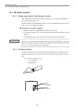
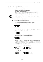
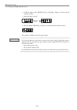
Страница 343: ...Maintenance and Check 16 3 3 Setting up Initializing Absolute encoder 16 14...


