


Drive set-up procedure
14.2.9 Model following control
14-48
CNC settings
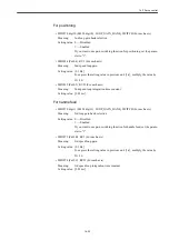
For feed axis
• MD37610 PROFIBUS_CTRL_CONFIG (For each Servo axis)
Meaning:
CNC feed mode transmission to a drive
Setting value: 0 --- Disabled
1 --- Enabled
Assign "1" (Enabled) to this parameter when model following control is
used.
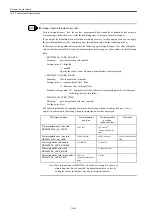
Note: Set this parameter to "Disabled" for Spindle; otherwise, you cannot
change over Spindle drive parameters (DBX21.0-2) from PLC.
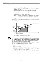
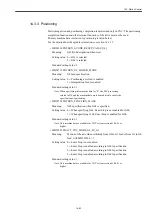
For Servo drive
• MD3046 digit 3 (Pn110 digit 3) SWITCH_ONLINE_AUTO_TUNING (For each axis)
Meaning:
Model following control (MFC) selection
Setting value: 0 --- Model following control is disabled.
1 --- Rigid model following control is carried out.
(2 --- 2-inertia model following control is carried out. You need to study
separately whether or not to use 2-inertia model following control.)
• MD3527 digit 0 (Pn81B digit 0) MASK_MFC_BANKSEL_0_3 (For each axis)
Meaning:
Model Following Control (MFC) bank 0 mask
Setting value: (0 --- Model following control is enabled.)
1 --- Model following control is disabled.
Note: Since model following control is to be used only for positioning, dis-
able the bank 0 by default.
• MD3527 digit 1 (Pn81B digit 1) MASK_MFC_BANKSEL_0_3 (For each axis)
Meaning:
Model Following Control (MFC) bank 1 mask
Setting value: 0 --- Model following control is enabled.
(1 --- Model following control is disabled.)
Note: Since model following control is to be used only for positioning,
enable the bank 1 (for positioning.)
• MD3527 digit 2 (Pn81B digit 2) MASK_MFC_BANKSEL_0_3 (For each axis)
Meaning:
Model Following Control (MFC) bank 2 mask
Setting value: (0 --- Model following control is enabled.)
1 --- Model following control is disabled.
Note: Since model following control is to be used only for positioning, dis-
able the bank 2 (for cutting feed.)
Содержание CNC Series
Страница 1: ...Maintenance Manual Serviceman Handbook MANUAL No NCSIE SP02 19 Yaskawa Siemens CNC Series...
Страница 26: ...Part 1 Hardware...
Страница 38: ...System Configuration 1 2 3 Spindle motor designations 1 12...
Страница 58: ...Installing the control panels 2 3 5 Installing lightning surge absorbers 2 20...
Страница 62: ...Installing the motors 3 4...
Страница 84: ...Connection method 4 3 2 Setting the rotary switches on the inverters and servo units 4 22...
Страница 96: ...Part 2 Software...
Страница 102: ...Software configuration 6 6...
Страница 103: ...7 1 Chapter 7 Backup 7 1 How to archive 7 2 7 2 Network settings 7 7 7 2 1 YS 840DI settings 7 7 7 2 2 PC settings 7 14...
Страница 105: ...7 1 How to archive 7 3 3 Select the Workpieces folder 4 Click on Archive File which is one of the right side keys...
Страница 113: ...7 2 Network settings 7 11 8 Click on the radio button to the left of Specify an IP address...
Страница 121: ...7 2 Network settings 7 19...
Страница 122: ...Part 3 PLC...
Страница 154: ...Part 4 Setting up and maintenance...
Страница 160: ...Overview of System 10 1 2 Basic operation 10 6...
Страница 204: ...How to use Digital Operation 12 2 9 Setting the password setting for write prohibit 12 32...
Страница 327: ...Error and Troubleshooting 15 4...
Страница 328: ...15 1 Errors without Alarm Display and Troubleshooting 15 5...
Страница 329: ...Error and Troubleshooting 15 6...
Страница 343: ...Maintenance and Check 16 3 3 Setting up Initializing Absolute encoder 16 14...


