


Drive system overview 1
13.2.2 How to control machine data and parameters
13-4
13.2.2 How to control machine data and parameters
In YS840DI system, each drive controls parameters that the drive uses. Since the parameters
are stored in the nonvolatile memory in the drive, the drive parameters MD3000-MD8999 in
previous table can be set either from the CNC screen or from the Digital operator for the
drive. However, the values are stored inside the drive and CNC only displays the values.
Parameters MD0-MD2999 can be displayed on the drive parameter screen, but can’t be set
from the screen. CNC machine data are controlled in the memory inside CNC.
13.2.3 Activation condition of machine data and parameters
For each machine data or parameter to be changed from the CNC display, some of the fol-
lowing conditions are also displayed to indicate how to activate the parameter.
• po: Parameter becomes active either when CNC power is turned on/off or [NCK Reset]
is entered.
• cf: Parameter becomes active when [Set MD Active] is entered.
• re: Parameter becomes active when CNC panel reset key is pressed.
• im: Parameter becomes active imidiately when a value is entered.
Especially for drive-control parameters MD3000-MD8999, "po" or "im" is indicated.
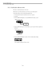
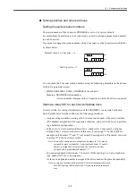
13.2.4 How to set machine data and parameters
Previously, a number is assigned to each parameter; however, in this YS 840DI system, each
of the numbers to be assigned is constructed differently according to applications. Espe-
cially, machine data and parameters for each axis are constructed as following
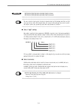
■
:
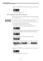
Drive parameters (MD0-MD8999) and
axis MD (MD30000-MD38
□□□□
)
Each axis has its own parameter screen. With the same number, the same parameters are
assigned. You can change over parameter screens by using function keys.
•
MD918 PROFIBUS_NODE_ADDRESS (for each axis)
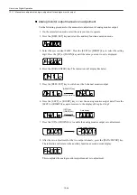
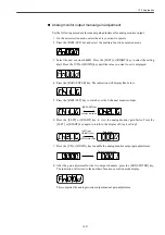
Other machine data section
As to machine data associated with each axis, one number represents an array for 1st axis to
n-th axis ([n] is displayed). The order of axis number (n-th axis) corresponding to [0] and [1]
are defined in MD10000 and MD10002.
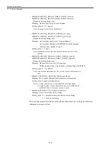
EXAMPLE
Содержание CNC Series
Страница 1: ...Maintenance Manual Serviceman Handbook MANUAL No NCSIE SP02 19 Yaskawa Siemens CNC Series...
Страница 26: ...Part 1 Hardware...
Страница 38: ...System Configuration 1 2 3 Spindle motor designations 1 12...
Страница 58: ...Installing the control panels 2 3 5 Installing lightning surge absorbers 2 20...
Страница 62: ...Installing the motors 3 4...
Страница 84: ...Connection method 4 3 2 Setting the rotary switches on the inverters and servo units 4 22...
Страница 96: ...Part 2 Software...
Страница 102: ...Software configuration 6 6...
Страница 103: ...7 1 Chapter 7 Backup 7 1 How to archive 7 2 7 2 Network settings 7 7 7 2 1 YS 840DI settings 7 7 7 2 2 PC settings 7 14...
Страница 105: ...7 1 How to archive 7 3 3 Select the Workpieces folder 4 Click on Archive File which is one of the right side keys...
Страница 113: ...7 2 Network settings 7 11 8 Click on the radio button to the left of Specify an IP address...
Страница 121: ...7 2 Network settings 7 19...
Страница 122: ...Part 3 PLC...
Страница 154: ...Part 4 Setting up and maintenance...
Страница 160: ...Overview of System 10 1 2 Basic operation 10 6...
Страница 204: ...How to use Digital Operation 12 2 9 Setting the password setting for write prohibit 12 32...
Страница 327: ...Error and Troubleshooting 15 4...
Страница 328: ...15 1 Errors without Alarm Display and Troubleshooting 15 5...
Страница 329: ...Error and Troubleshooting 15 6...
Страница 343: ...Maintenance and Check 16 3 3 Setting up Initializing Absolute encoder 16 14...


