


10.1 Screen operation
10-3
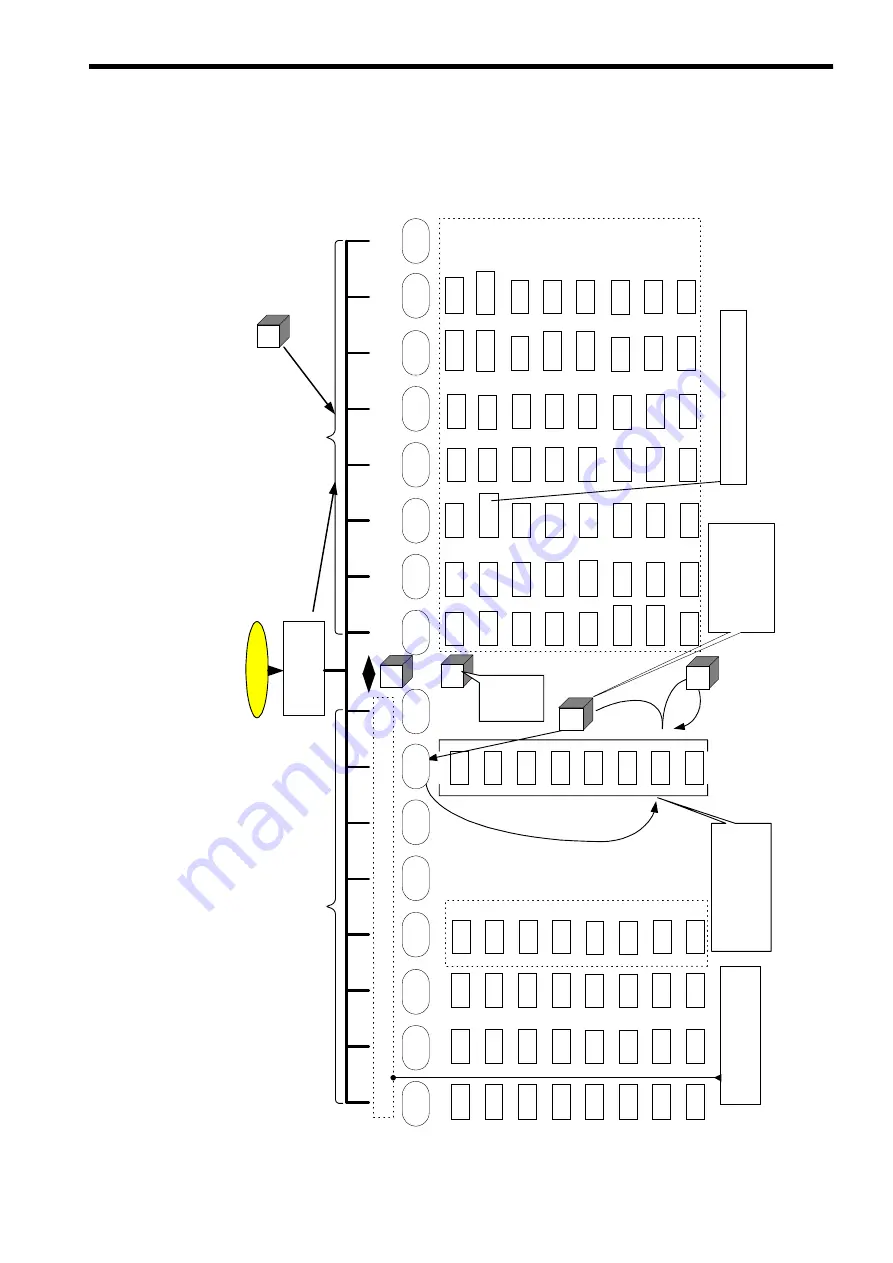
10.1.2 Basic operation
The following screen tree shows the transition of screen states.
Power ON
HS5
HS6
HS7
HS8
HS1
HS2
HS3
HS4
Setting
HS4
Initial screen
(Wallpaper)
When power is supplied, ShopMill
screen displays.
NC
* 2
PC CARD
M
You can return to the ShopMill
screen from any screen.
II
V
V
V
Service *1
HS1
Diagnosis
HS2
Start-up
HS3
Data
selection
Interfac
e
Alarm
Message
Alarm
log
PLC
status
Service
display
Remote
diagnosi
s
Machine
data
User
display
NC
Drive
servo
MMC
PLC
Tool
indication
setting
Input
Output
File
management
Manual
operation
Automatic
operation
Program
management
Program
Edit
User
message
Tool/Work
coordinate
system
COMMON
Simulation
Program
modificatio
n
STEP7
HS5
HS6
HS7
HS8
Setting
data
User
data
*1 If the exclusive customer screen
is added, the alignment between
HS1 and HS8 may be changed.
T,S,M...
...
Zero offset
origin
setting
Work origin
offset
Measur
ing tool
MDA
Positioning
Face
milling
Setting
Soft
switch
Program
control
Block
searching
Program
modificatio
n
Tool list
Tool
abrasion
List of
Compensati
on value
Magazine
Origin
offset
R
parameter
Position
batch
Running
hour
*2 If the PC card driver is connected, this F
key is displayed.
By pressing this key, only
the Function key display is
changed from HS1
(Service) until HS8
(Auxiliary) but the screen
is not changed.
When the Process key is
pressed down, there displays
each screen sequently and
subsequently the Function key
display is changed to
correspond each screen.
ShopMill
Standard
The level of
each screen
is changed
from the
lower to the
upper.
Содержание CNC Series
Страница 1: ...Maintenance Manual Serviceman Handbook MANUAL No NCSIE SP02 19 Yaskawa Siemens CNC Series...
Страница 26: ...Part 1 Hardware...
Страница 38: ...System Configuration 1 2 3 Spindle motor designations 1 12...
Страница 58: ...Installing the control panels 2 3 5 Installing lightning surge absorbers 2 20...
Страница 62: ...Installing the motors 3 4...
Страница 84: ...Connection method 4 3 2 Setting the rotary switches on the inverters and servo units 4 22...
Страница 96: ...Part 2 Software...
Страница 102: ...Software configuration 6 6...
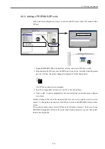
Страница 103: ...7 1 Chapter 7 Backup 7 1 How to archive 7 2 7 2 Network settings 7 7 7 2 1 YS 840DI settings 7 7 7 2 2 PC settings 7 14...
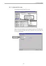
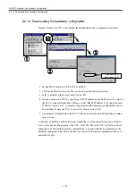
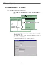
Страница 105: ...7 1 How to archive 7 3 3 Select the Workpieces folder 4 Click on Archive File which is one of the right side keys...
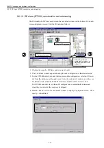
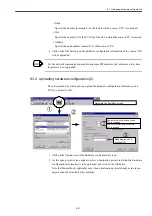
Страница 113: ...7 2 Network settings 7 11 8 Click on the radio button to the left of Specify an IP address...
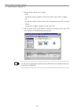
Страница 121: ...7 2 Network settings 7 19...
Страница 122: ...Part 3 PLC...
Страница 154: ...Part 4 Setting up and maintenance...
Страница 160: ...Overview of System 10 1 2 Basic operation 10 6...
Страница 204: ...How to use Digital Operation 12 2 9 Setting the password setting for write prohibit 12 32...
Страница 327: ...Error and Troubleshooting 15 4...
Страница 328: ...15 1 Errors without Alarm Display and Troubleshooting 15 5...
Страница 329: ...Error and Troubleshooting 15 6...
Страница 343: ...Maintenance and Check 16 3 3 Setting up Initializing Absolute encoder 16 14...


