


14.1 Fundamental settings
14-13
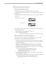
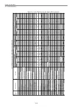
Definitions of logical axis numbers and names in
the whole system.
MD10000 MD10002
6th axis [5]
7th axis [6]
8th axis [7]
9th axis [8]
10th axis [9]
11th axis [10]
12th axis [11]
AX1
AX2
AX3
AX4
AX5
AX6
AX7
AX8
AX9
AX10
AX11
AX12
1st axis [0]
2nd axis [1]
3rd axis [2]
4th axis [3]
5th axis [4]
Definitions of logical axis numbers and
names of the 1st group.
MD20070
MD20080
[
0
]:
3
[
1
]:
4
[
2
]:
5
[
3
]:
9
[
4
]:
1
[
0
]:
X
[
1
]:
Y
[
2
]:
Z
[
3
]:
A
[
4
]:
SP
Definitions of logical axis numbers and
names of the 2nd group.
MD20070
MD20080
[
3
]:
11
[
4
]:
2
[
3
]:
A
[
4
]:
SP
Definitions of geometry axis numbers and names
of the 1st channel
MD20050
MD20060
[
0
]:
1
[
1
]:
2
[
2
]:
3
[
0
]:
X
[
1
]:
Y
[
2
]:
Z
Definitions of geometry axis numbers and names
of the 2nd channel
MD20050
MD20060
[
0
]:
1
[
1
]:
2
[
2
]:
3
[
0
]:
X
[
1
]:
Y
[
2
]:
Z
[
0
]:
6
[
1
]:
7
[
2
]:
8
[
0
]:
X
[
1
]:
Y
[
2
]:
Z
Physical axis configuration (Drive configuration)
S
W
No=4
Hardware
configuration
first address (MD19050)
Converter 1
PROFIBUS
ID=6
Drive 1
(
SP1
)
S
W
No=0
Drive 2
(
X1
)
S
W
No=1
Drive 3
(
Y1
)
S
W
No=2
Drive 4
(
Z1
)
S
W
No=3
Drive 5
(
A1
)
272
292
312
332
352
Hardware
configuration
first address (MD19050)
Converter 2
PROFIBUS
ID=7
Drive 1
(
SP2
)
S
W
No=0
Drive 2
(
X2
)
S
W
No=1
Drive 3
(
Y2
)
S
W
No=2
Drive 4
(
Z2
)
S
W
No=3
372
392
412
432
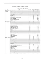
Relations between logical and physical axis numbers, and settings of active
and inactive axes in the whole system
Drive
Motor encoder
External encoder
Logical
axis name
Logical address
Logical address
Logical address
MD10000
MD30110
MD30220
[
0
]
MD30220
[
1
]
MD30130
:
SP1
:
SP2
:
X1
:
Y1
:
Z1
:
X2
:
Y2
:
A1
:
B1
:
A2
:
B2
:
Z2
SP1
SP2
X1
Y1
Z1
X2
Y2
A1
B1
A2
B2
Z2
1
6
2
3
4
7
8
9
5
1
6
2
3
4
7
8
9
5
1
6
2
3
4
7
8
9
5
1
1
1
1
1
1
1
1
1
0
0
0
Invalid setting
Invalid setting
Invalid setting
Invalid setting
Invalid setting
Invalid setting
Invalid setting
Invalid setting
Invalid setting
In the order of
addresses during
hardware configuration
A2 axis is to be defined
although it is a simulation axis
(without a drive).
To be set to 0 because A2 is a
simulation axis (without a
drive).
Definition of the sequence of
X, Y, and Z-axis defined with
MD20070.
Axis enable/disable
Содержание CNC Series
Страница 1: ...Maintenance Manual Serviceman Handbook MANUAL No NCSIE SP02 19 Yaskawa Siemens CNC Series...
Страница 26: ...Part 1 Hardware...
Страница 38: ...System Configuration 1 2 3 Spindle motor designations 1 12...
Страница 58: ...Installing the control panels 2 3 5 Installing lightning surge absorbers 2 20...
Страница 62: ...Installing the motors 3 4...
Страница 84: ...Connection method 4 3 2 Setting the rotary switches on the inverters and servo units 4 22...
Страница 96: ...Part 2 Software...
Страница 102: ...Software configuration 6 6...
Страница 103: ...7 1 Chapter 7 Backup 7 1 How to archive 7 2 7 2 Network settings 7 7 7 2 1 YS 840DI settings 7 7 7 2 2 PC settings 7 14...
Страница 105: ...7 1 How to archive 7 3 3 Select the Workpieces folder 4 Click on Archive File which is one of the right side keys...
Страница 113: ...7 2 Network settings 7 11 8 Click on the radio button to the left of Specify an IP address...
Страница 121: ...7 2 Network settings 7 19...
Страница 122: ...Part 3 PLC...
Страница 154: ...Part 4 Setting up and maintenance...
Страница 160: ...Overview of System 10 1 2 Basic operation 10 6...
Страница 204: ...How to use Digital Operation 12 2 9 Setting the password setting for write prohibit 12 32...
Страница 327: ...Error and Troubleshooting 15 4...
Страница 328: ...15 1 Errors without Alarm Display and Troubleshooting 15 5...
Страница 329: ...Error and Troubleshooting 15 6...
Страница 343: ...Maintenance and Check 16 3 3 Setting up Initializing Absolute encoder 16 14...


