


269
APPENDIX H
(reference)
3.1. Spare Parts, Tools and Accessories
For each truck the plant supplies single spare parts kit-0, tools and accessories.
On the customer’s request the following can be added:
- warranty spare parts kit for the power unit consisting of the tools, accessories and spare
parts;
- a set of accessories (mobile lamp, manual-operated pump for fuel transfer, lever type
grease gun);
- tools kit (fitting and assembly tools, manufactured according to GOST requirements).
Guarantee period of spare parts kit conservation is three years, if stored in a closed room.
The plant is constantly improving the truck, that is why the articles in the spare parts kit
can vary. The exact list is specified in the shipping documentation supplied with each truck.
When shipping a truck, spare parts kit-0 is put into a spare parts kit transportation box.
Recommendations of operational tools and accessories breakdown for the truck are given in this
paragraph.
The manufacturing plant is making such a breakdown for the items mantled on the truck
chassis.
Truck chassis has no fire extinguisher, first aid kit, emergency stop sign (can be supplied
if additionally ordered).
When driving the truck, the driver can breakdown the tools as it is convenient for him.
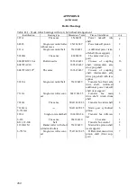
Table H.1 - Tools and Accessories Breakdown for Ural Trucks
Position No.
in the figure
Item
Quantity
Tools kit in the kitbag 12 (see figure I.1)
1
1000 g locksmith’s hammer
1*
2
Chipper
1*
3
Locksmith’s driftbolt
1*
4
A kit of unseating tools for tubes dismantle
1
5
50 socket head
1*
1
6
Wrench for 65-70 round nuts
1
7
24Х27 box wrench
1*
8
Fitting tube
1
9
27X38 socket wrench for wheels
1
10
19Х22 special socket wrench
1
11
30Х32 socket wrench
1
12
Kitbag
1
13
Socket wrench 6
1
Содержание 4320M
Страница 1: ...URAL 4320М TRUCK and its Modifications ...
Страница 34: ...33 Figure 17 Truck Ural 43206 0551 71 Figure 18 Truck Ural 43206 3111 79 Figure 19 Truck Ural 43206 3511 79 ...
Страница 106: ......
Страница 110: ......
Страница 159: ...156 Figure 123 Engine Electronic Control Unit Wiring Scheme ...
Страница 165: ......
Страница 167: ......
Страница 173: ......
Страница 177: ...Figure 140 Installation of left and right side safety devices 171 ...
Страница 201: ......
Страница 203: ......
Страница 205: ......
Страница 207: ......
Страница 209: ......
Страница 212: ......
Страница 214: ......
Страница 216: ......
Страница 218: ......
Страница 220: ......
Страница 222: ......
Страница 224: ......
Страница 226: ......
Страница 228: ......
Страница 230: ......
Страница 232: ......
Страница 234: ......
Страница 236: ......
Страница 238: ......
Страница 240: ......
Страница 242: ......
Страница 244: ......
Страница 246: ......
Страница 248: ......
Страница 250: ......
Страница 252: ......
Страница 254: ......
Страница 256: ......
Страница 257: ...223 ...
Страница 259: ......
Страница 315: ...280 ...
Страница 317: ......