


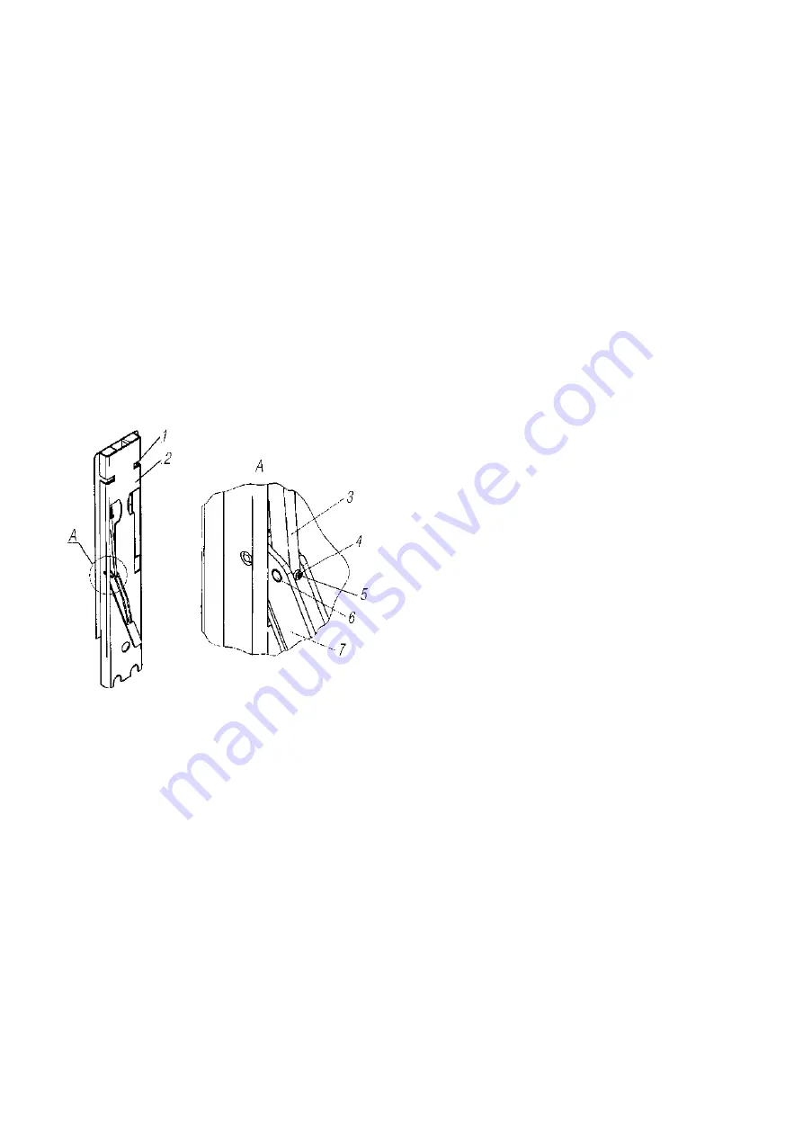
For adjustment implementation:
1. Move the handle 7 in the position OPENED.
2. Remove the screw 5 with the spring washer 4.
3. Push the tappet axle 6 out of the handle hole 7.
4. Remove the tappet 3 from the handle groove 7.
5. Moving the tappet 3 round its axis for whole number of rotations, implement move-
ment of the lock 1 on the required value in the required direction (on rotation of the tappet corre-
sponds to 2mm of the lock movement):
-to move the lock 1 down screw the turn 3 off;
-to move the lock 1 down screw the turn 3 out;
6. Put the tappet 3 in the handle groove 7, combining holes on the handle with the tappet.
7. Put the tappet axle 6 in the handle hole 7, combining the axle screw hole with the tap-
pet hole 3.
8. By rack closing and strut locking, check accuracy of adjustment. If necessary, repeat
clauses 1, 2, 4-9.
9. Move the handle 7 in the position OPENED.
10. Turn the screw with the spring washer 4 in the screw hole of the tappet 3.
4.7.3.2 Side safety devices (SFD)
are shown in figure 140, provide efficient protection
at full length of the vehicle, unprotected road users from falling under the vehicle on the side.
Vehicle SFD includes right and left SFD, each of them consists of two barriers: front (below the
cab) and rear (behind the cab).
When lowering the spare wheel holder, it is necessary to dismantle the right rear SFD:
- turn away fastening bolts of SFD brackets to upper connecting shackles, located on in-
side of the barrier;
- remove SFD from the lower hooks of brackets.
Installation of the rear barrier provide in the reversed order.
170
1-Lock; 2-housing strut; 3-tappet; 4-spring washer;
5-screw; 6-tappet axle; 7-handle
Figure 139 - Platform strut with
the device adjustment
Содержание 4320M
Страница 1: ...URAL 4320М TRUCK and its Modifications ...
Страница 34: ...33 Figure 17 Truck Ural 43206 0551 71 Figure 18 Truck Ural 43206 3111 79 Figure 19 Truck Ural 43206 3511 79 ...
Страница 106: ......
Страница 110: ......
Страница 159: ...156 Figure 123 Engine Electronic Control Unit Wiring Scheme ...
Страница 165: ......
Страница 167: ......
Страница 173: ......
Страница 177: ...Figure 140 Installation of left and right side safety devices 171 ...
Страница 201: ......
Страница 203: ......
Страница 205: ......
Страница 207: ......
Страница 209: ......
Страница 212: ......
Страница 214: ......
Страница 216: ......
Страница 218: ......
Страница 220: ......
Страница 222: ......
Страница 224: ......
Страница 226: ......
Страница 228: ......
Страница 230: ......
Страница 232: ......
Страница 234: ......
Страница 236: ......
Страница 238: ......
Страница 240: ......
Страница 242: ......
Страница 244: ......
Страница 246: ......
Страница 248: ......
Страница 250: ......
Страница 252: ......
Страница 254: ......
Страница 256: ......
Страница 257: ...223 ...
Страница 259: ......
Страница 315: ...280 ...
Страница 317: ......