


The pet cock 11, located on the right engine water pipe, shall be opened during operation
at sub-zero air temperatures. In summer the heating unit shall be unplugged from the cooling sys-
tem, by closing the pet cock 11.
When using water as coolant at sub-zero air temperatures, close the heating unit tap be-
fore filling the cooling system to prevent cold water penetration in the heating unit radiator and its
freezing.
The cab is ventilated through heating unit hatches, apertures in turning and drop door
windows. Upon insufficient air ventilation in the cab, open the external hatch and turn on the fan.
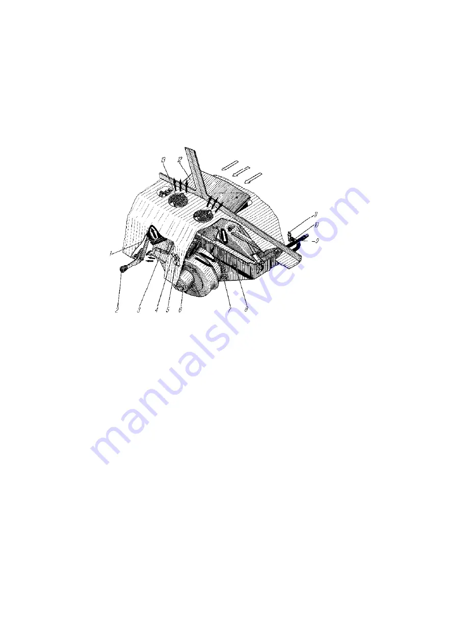
1-warm-air feed pipe for windshield demist; 2-joystick of the external hatch drive gear; 3-warm
air distributor; 4- gear lever of the
flap of the warm air distributor; 5-gear lever of the internal hatch; 6-
electric motor assembled with fan; 7-inner hatch lid; 8-heating unit radiator; 9-water discharge pipe from
the heating unit radiator; 10-water discharge pipe; 11-pet cock; 12-external hatch lid; 13-vent
Figure 125
–
Operating circuit of the cab heater and the glass bead blasting
4.7.1.5 Cab heating and ventilation system of the cabover truck
is designed to heat the
cab and consists of the radiator, included in the engine cooling system and the engine starting
heater system, the heater tap, the fan and the air duct system with adjustable flaps to distribute air
on the windshield, side windows and the cab floor. System operation is realised by levers, located
on the control panel.
The lever 11, in accordance with figure 28, regulates air distribution on the windshield.
When the lever is in the right position, flaps are closed, in the left – opened (air is distributed on
the windshield).
The lever 12 regulates air supply in the leg area of the driver and passengers. When the
lever is in the right position, flaps are closed, in the left – opened (air is distributed in the leg area
of the driver and passengers).
166
Содержание 4320M
Страница 1: ...URAL 4320М TRUCK and its Modifications ...
Страница 34: ...33 Figure 17 Truck Ural 43206 0551 71 Figure 18 Truck Ural 43206 3111 79 Figure 19 Truck Ural 43206 3511 79 ...
Страница 106: ......
Страница 110: ......
Страница 159: ...156 Figure 123 Engine Electronic Control Unit Wiring Scheme ...
Страница 165: ......
Страница 167: ......
Страница 173: ......
Страница 177: ...Figure 140 Installation of left and right side safety devices 171 ...
Страница 201: ......
Страница 203: ......
Страница 205: ......
Страница 207: ......
Страница 209: ......
Страница 212: ......
Страница 214: ......
Страница 216: ......
Страница 218: ......
Страница 220: ......
Страница 222: ......
Страница 224: ......
Страница 226: ......
Страница 228: ......
Страница 230: ......
Страница 232: ......
Страница 234: ......
Страница 236: ......
Страница 238: ......
Страница 240: ......
Страница 242: ......
Страница 244: ......
Страница 246: ......
Страница 248: ......
Страница 250: ......
Страница 252: ......
Страница 254: ......
Страница 256: ......
Страница 257: ...223 ...
Страница 259: ......
Страница 315: ...280 ...
Страница 317: ......