


4. STARTUP
4 - 6
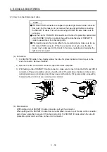
(5) Stop
Turn off the servo-on command after the servo motor has stopped, and then switch the power off.
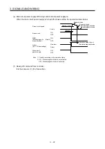
If any of the following situations occurs, the servo amplifier suspends the running of the servo motor and
brings it to a stop.
Refer to section 3.10 for the servo motor with an electromagnetic brake.
Operation/command
Stopping
condition
Servo system
controller
Servo-off command
The base circuit is shut off and the servo motor coasts.
Ready-off command
The base circuit is shut off and the dynamic brake operates to
bring the servo motor to a stop.
Forced stop command
The servo motor decelerates to a stop with the command. [AL.
E7 Controller forced stop warning] occurs.
Servo amplifier
Alarm occurrence
The servo motor decelerates to a stop with the command. With
some alarms, however, the dynamic brake operates to bring the
servo motor to a stop. (Refer to section 8. (Note))
EM2 (Forced stop 2) off
The servo motor decelerates to a stop with the command. [AL.
E6 Servo forced stop warning] occurs. EM2 has the same device
as EM1 in the torque control mode. Refer to section 3.5 for EM1.
STO (STO1, STO2) off
The base circuit is shut off and the dynamic brake operates to
bring the servo motor to a stop.
Note. Only a list of alarms and warnings is listed in chapter 8. Refer to "MELSERVO-J4 Servo Amplifier
Instruction Manual (Troubleshooting)" for details of alarms and warnings.
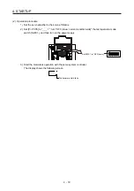
4.3 Switch setting and display of the servo amplifier
Switching to the test operation mode, deactivating control axes, and setting control axis No. are enabled with
switches on the servo amplifier.
On the servo amplifier display (three-digit, seven-segment LED), check the status of communication with the
servo system controller at power-on, and the axis number, and diagnose a malfunction at occurrence of an
alarm.
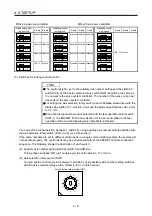
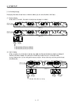
4.3.1 Switches
WARNING
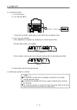
When switching the axis selection rotary switch (SW1) and auxiliary axis number
setting switch (SW2), use an insulated screw driver. Do not use a metal screw
driver. Touching patterns on electronic boards, lead of electronic parts, etc. may
cause an electric shock.
POINT
Turning "ON (up)" all the control axis setting switches (SW2) enables an
operation mode for manufacturer setting and displays "off". The mode is not
available. Set the control axis setting switches (SW2) correctly according to this
section.
Cycling the main circuit power supply and control circuit power supply enables
the setting of each switch.
Содержание MR-J4W2-0303B6
Страница 17: ...8 App 16 Status of general purpose AC servo products for compliance with the China RoHS directive App 58 ...
Страница 39: ...2 INSTALLATION 2 8 MEMO ...
Страница 97: ...4 STARTUP 4 20 MEMO ...
Страница 181: ...6 NORMAL GAIN ADJUSTMENT 6 28 MEMO ...
Страница 235: ...9 DIMENSIONS 9 6 MEMO ...
Страница 245: ...10 CHARACTERISTICS 10 10 MEMO ...
Страница 309: ...13 USING STO FUNCTION 13 14 MEMO ...
Страница 365: ...15 USING A DIRECT DRIVE MOTOR 15 24 MEMO ...
Страница 389: ...16 FULLY CLOSED LOOP SYSTEM 16 24 MEMO ...
Страница 461: ...17 APPLICATION OF FUNCTIONS 17 72 MEMO ...
Страница 556: ...APPENDIX App 41 ...
Страница 585: ...MEMO ...