


5. PARAMETERS
5 - 23
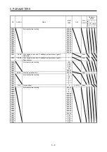
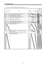
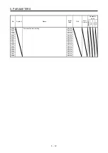
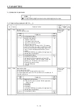
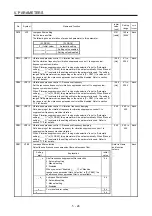
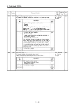
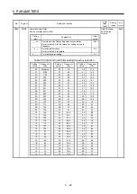
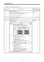
5.2.2 Gain/filter setting parameters ([Pr. PB_ _ ])
No.
Symbol
Name and function
Initial
value
[unit]
Setting
range
Each/
Common
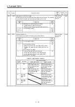
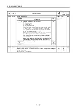
PB01
FILT
Adaptive tuning mode (adaptive filter II)
Set the adaptive tuning.
All axes cannot be simultaneously enabled for this function. Set for each axis to use.
Refer to Name
and function
column.
Each
Setting
digit
Explanation
Initial
value
_ _ _ x
Filter tuning mode selection
Select the adjustment mode of the machine resonance
suppression filter 1. Refer to section 7.1.2 for details.
0: Disabled
1: Automatic setting
2: Manual setting
0h
_ _ x _
For manufacturer setting
0h
_ x _ _
0h
x _ _ _
Tuning accuracy selection
0: Standard
1: High accuracy
The frequency is estimated more accurately in the high
accuracy mode compared to the standard mode. However,
the tuning sound may be larger in the high accuracy mode.
This digit is available with servo amplifier with software
version C5 or later.
0h
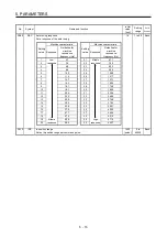
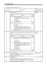
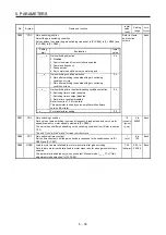
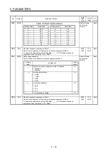
PB02
VRFT
Vibration suppression control tuning mode (advanced vibration suppression control II)
This is used to set the vibration suppression control tuning. Refer to section 7.1.5 for
details.
All axes cannot be simultaneously enabled for this function. Set for each axis to use.
Refer to Name
and function
column.
Each
Setting
digit
Explanation
Initial
value
_ _ _ x
Vibration suppression control 1 tuning mode selection
Select the tuning mode of the vibration suppression control
1.
0: Disabled
1: Automatic setting
2: Manual setting
0h
_ _ x _
Vibration suppression control 2 tuning mode selection
Select the tuning mode of the vibration suppression control
2. To enable the digit, select "3 inertia mode (_ _ _ 1)" of
"Vibration suppression mode selection" in [Pr. PA24
Function selection A-4].
0: Disabled
1: Automatic setting
2: Manual setting
0h
_ x _ _
For manufacturer setting
0h
x _ _ _
0h
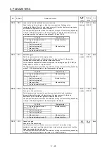
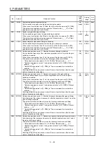
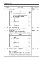
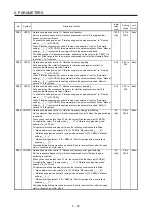
PB03 TFBGN Torque feedback loop gain
Set a torque feedback loop gain in the continuous operation to torque control mode.
Decreasing the setting value will also decrease a collision load during continuous
operation to torque control mode.
Setting a value less than 6 rad/s will be 6 rad/s.
18000
[rad/s]
0 to
18000
Each
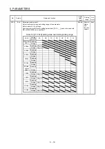
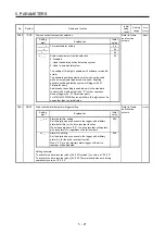
PB04
FFC
Feed forward gain
Set the feed forward gain.
When the setting is 100%, the droop pulses during operation at constant speed are
nearly zero. However, sudden acceleration/deceleration will increase the overshoot.
As a guideline, when the feed forward gain setting is 100%, set 1 s or more as the
acceleration time constant up to the rated speed.
0
[%]
0 to
100
Each
Содержание MR-J4W2-0303B6
Страница 17: ...8 App 16 Status of general purpose AC servo products for compliance with the China RoHS directive App 58 ...
Страница 39: ...2 INSTALLATION 2 8 MEMO ...
Страница 97: ...4 STARTUP 4 20 MEMO ...
Страница 181: ...6 NORMAL GAIN ADJUSTMENT 6 28 MEMO ...
Страница 235: ...9 DIMENSIONS 9 6 MEMO ...
Страница 245: ...10 CHARACTERISTICS 10 10 MEMO ...
Страница 309: ...13 USING STO FUNCTION 13 14 MEMO ...
Страница 365: ...15 USING A DIRECT DRIVE MOTOR 15 24 MEMO ...
Страница 389: ...16 FULLY CLOSED LOOP SYSTEM 16 24 MEMO ...
Страница 461: ...17 APPLICATION OF FUNCTIONS 17 72 MEMO ...
Страница 556: ...APPENDIX App 41 ...
Страница 585: ...MEMO ...