


3. SIGNALS AND WIRING
3 - 14
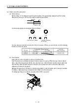
3.5 Signal (device) explanations
For the I/O interfaces (symbols in I/O division column in the table), refer to section 3.8.
The pin numbers in the connector pin No. column are those in the initial status.
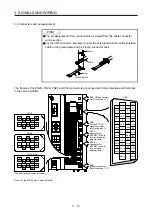
3.5.1 Input device
Device Symbol
Connector
pin No.
Function and application
I/O
division
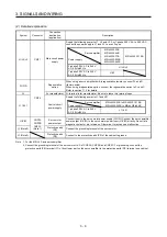
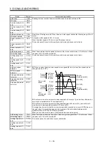
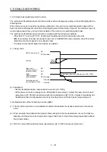
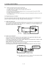
Forced stop 2
EM2
(CN3-10)
Turn off EM2 (open between commons) to decelerate the servo motor to a stop
with commands.
Turn EM2 on (short between commons) in the forced stop state to reset that
state.
Set [Pr. PA04] to "2 1 _ _" to disable EM2.
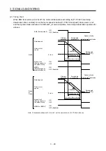
The following shows the setting of [Pr. PA04].
DI-1
[Pr. PA04]
setting
EM2/EM1
Deceleration method
EM2 or EM1 is off
Alarm occurred
0 0 _ _
EM1
MBR (Electromagnetic
brake interlock) turns off
without the forced stop
deceleration.
MBR (Electromagnetic
brake interlock) turns off
without the forced stop
deceleration.
2 0 _ _
EM2
MBR (Electromagnetic
brake interlock) turns off
after the forced stop
deceleration.
MBR (Electromagnetic
brake interlock) turns off
after the forced stop
deceleration.
0 1 _ _
Not using
EM2 and
EM1
MBR (Electromagnetic
brake interlock) turns off
without the forced stop
deceleration.
2 1 _ _
Not using
EM2 and
EM1
MBR (Electromagnetic
brake interlock) turns off
after the forced stop
deceleration.
EM2 and EM1 are mutually exclusive.
EM2 has the same device as EM1 in the torque control mode.
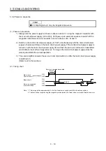
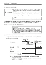
Forced stop 1
EM1
(CN3-10)
When using EM1, set [Pr. PA04] to "0 0 _ _" to enable EM1.
When EM1 is turned off (open between commons), the base circuit shuts off,
and the dynamic brake operates to decelerate the servo motor to a stop.
The forced stop will be reset when EM1 is turned on (short between commons).
Set [Pr. PA04] to "0 1 _ _" to disable EM1.
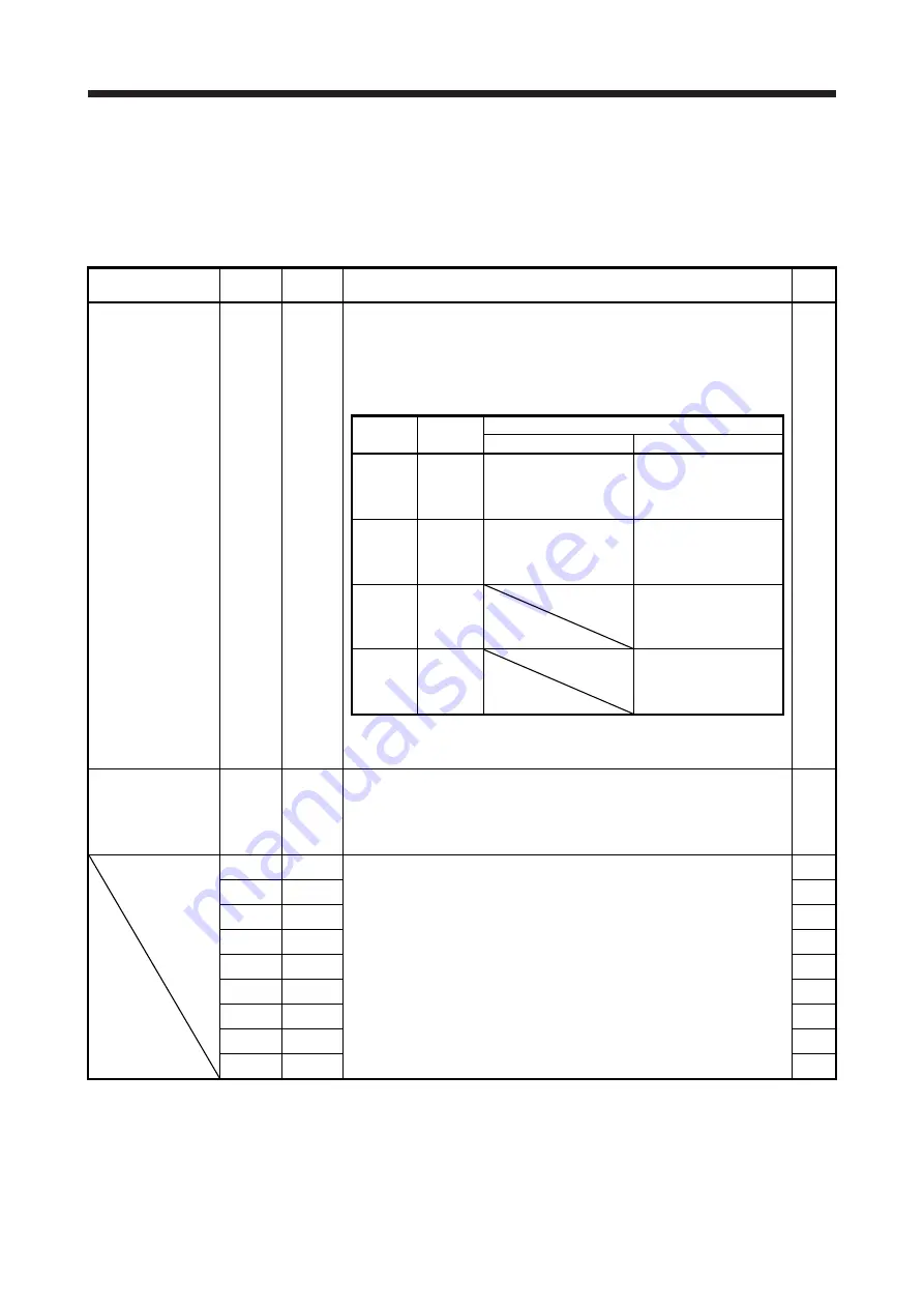
DI-1
DI1-A CN3-7
Devices can be assigned for these devices with controller setting. For devices
that can be assigned, refer to the controller instruction manual. You can assign
the following devices with MR-J4 series compatible controllers (R_MTCPU,
Q17_DSCPU, RD77MS_, and QD77MS_)
DI1-A: FLS for A-axis (Upper stroke limit)
DI2-A: RLS for A-axis (Lower stroke limit)
DI3-A: DOG for A-axis (Proximity dog)
DI1-B: FLS for B-axis (Upper stroke limit)
DI2-B: RLS for B-axis (Lower stroke limit)
DI3-B: DOG for B-axis (Proximity dog)
DI1-C: FLS for C-axis (Upper stroke limit)
DI2-C: RLS for C-axis (Lower stroke limit)
DI3-C: DOG for C-axis (Proximity dog)
DI-1
DI2-A CN3-8
DI-1
DI3-A CN3-9
DI-1
DI1-B CN3-20
DI-1
DI2-B CN3-21
DI-1
DI3-B CN3-22
DI-1
DI1-C CN3-1
DI-1
DI2-C CN3-2
DI-1
DI3-C CN3-15
DI-1
Содержание MR-J4W2-0303B6
Страница 17: ...8 App 16 Status of general purpose AC servo products for compliance with the China RoHS directive App 58 ...
Страница 39: ...2 INSTALLATION 2 8 MEMO ...
Страница 97: ...4 STARTUP 4 20 MEMO ...
Страница 181: ...6 NORMAL GAIN ADJUSTMENT 6 28 MEMO ...
Страница 235: ...9 DIMENSIONS 9 6 MEMO ...
Страница 245: ...10 CHARACTERISTICS 10 10 MEMO ...
Страница 309: ...13 USING STO FUNCTION 13 14 MEMO ...
Страница 365: ...15 USING A DIRECT DRIVE MOTOR 15 24 MEMO ...
Страница 389: ...16 FULLY CLOSED LOOP SYSTEM 16 24 MEMO ...
Страница 461: ...17 APPLICATION OF FUNCTIONS 17 72 MEMO ...
Страница 556: ...APPENDIX App 41 ...
Страница 585: ...MEMO ...