1. FUNCTIONS AND CONFIGURATION
1 - 14
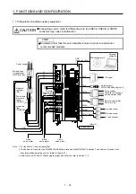
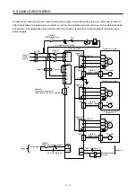
1.7 Configuration including auxiliary equipment
CAUTION
Connecting a servo motor for different axis to the CNP3A, CNP3B, or CNP3C
connector may cause a malfunction.
POINT
Equipment other than the servo amplifier and servo motor are optional or
recommended products.
CNP3B
CNP3A
D (Note 3)
CNP3C (Note 1)
CNP2
CNP1
W
U
V
W
U
V
W
U
V
Power factor
improving
reactor
(FR-HAL)
Line noise
filter
(FR-BSF01)
Power supply
Magnetic
contactor
(MC)
Molded-case
circuit breaker
(MCCB) or fuse
Personal
computer
Servo system
controller or Front axis
servo amplifier CN1B
Safety relay or
MR-J3-D05 safety logic unit
Rear servo amplifier
CN1A or Cap
CN3
CN5
(under the cover)
CN1B
CN2A
(Note 2)
CN2B
CN2C (Note 1)
Battery unit
CN1A
CN8
I/O signal
P+
L1
L2
L3
L21
L11
C
Regenerative
option
MR Configurator2
A-axis encoder
B-axis encoder
C-axis encoder
CN4
R S T
A-axis
servo motor
B-axis
servo motor
C-axis
servo motor
Note 1. For the MR-J4 3-axis servo amplifier
2. The battery unit consists of an MR-BT6VCASE battery case and five MR-BAT6V1 batteries. The battery unit is used in the
absolute position detection system. (Refer to chapter 12.)
3.
Always connect P+ and D. When using the regenerative option, refer to section 11.2.
Содержание MR-J4W2-0303B6
Страница 17: ...8 App 16 Status of general purpose AC servo products for compliance with the China RoHS directive App 58 ...
Страница 39: ...2 INSTALLATION 2 8 MEMO ...
Страница 97: ...4 STARTUP 4 20 MEMO ...
Страница 181: ...6 NORMAL GAIN ADJUSTMENT 6 28 MEMO ...
Страница 235: ...9 DIMENSIONS 9 6 MEMO ...
Страница 245: ...10 CHARACTERISTICS 10 10 MEMO ...
Страница 309: ...13 USING STO FUNCTION 13 14 MEMO ...
Страница 365: ...15 USING A DIRECT DRIVE MOTOR 15 24 MEMO ...
Страница 389: ...16 FULLY CLOSED LOOP SYSTEM 16 24 MEMO ...
Страница 461: ...17 APPLICATION OF FUNCTIONS 17 72 MEMO ...
Страница 556: ...APPENDIX App 41 ...
Страница 585: ...MEMO ...

