5. PARAMETERS
5 - 44
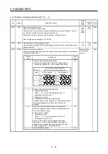
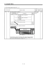
5.2.4 I/O setting parameters ([Pr. PD_ _ ])
No.
Symbol
Name and function
Initial
value
[unit]
Setting
range
Each/
Common
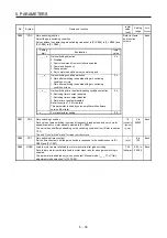
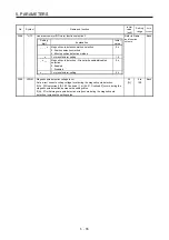
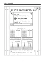
PD02
*DIA2
Input signal automatic on selection 2
Refer to Name
and function
column.
Each
Setting
digit
Explanation
Initial
value
HEX. BIN.
_ _ _ x
_ _ _ x
FLS (Upper stroke limit) selection
0: Disabled
1: Enabled
0h
_ _ x _
RLS (Lower stroke limit) selection
0: Disabled
1: Enabled
_ x _ _
For manufacturer setting
x _ _ _
_ _ x _
For manufacturer setting
0h
_ x _ _
0h
x _ _ _
0h
Convert the setting value into hexadecimal as follows.
0
BIN 0: Disabled (Use for an external input signal.)
BIN 1: Automatic on
Initial value
BIN HEX
Signal name
0
0
0 0 0
0
0
FLS (Upper stroke limit) selection
RLS (Lower stroke limit) selection
When performing a magnetic pole detection without using FLS (Upper stroke limit)
and RLS (Lower stroke limit), you can disable FLS and RLS by setting [Pr. PL08
Linear servo motor/DD motor function selection 3] to "_ 1 _ _".
Содержание MR-J4W2-0303B6
Страница 17: ...8 App 16 Status of general purpose AC servo products for compliance with the China RoHS directive App 58 ...
Страница 39: ...2 INSTALLATION 2 8 MEMO ...
Страница 97: ...4 STARTUP 4 20 MEMO ...
Страница 181: ...6 NORMAL GAIN ADJUSTMENT 6 28 MEMO ...
Страница 235: ...9 DIMENSIONS 9 6 MEMO ...
Страница 245: ...10 CHARACTERISTICS 10 10 MEMO ...
Страница 309: ...13 USING STO FUNCTION 13 14 MEMO ...
Страница 365: ...15 USING A DIRECT DRIVE MOTOR 15 24 MEMO ...
Страница 389: ...16 FULLY CLOSED LOOP SYSTEM 16 24 MEMO ...
Страница 461: ...17 APPLICATION OF FUNCTIONS 17 72 MEMO ...
Страница 556: ...APPENDIX App 41 ...
Страница 585: ...MEMO ...

