18. MR-J4W2-0303B6 SERVO AMPLIFIER
18 - 33
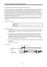
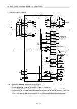
(c) Analog monitor block diagram
Droop
pulses
Speed
command
Position
control
Speed
control
PWM
Current
control
Current
command
Bus voltage
Speed
command
Current
detector
+
Servo motor
Encoder
Current feedback
Position feedback
M
Position command
received from
servo system
controller
Position feedback
data returned to
servo system
controller
Differen-
tiation
Differen-
tiation
Feedback position
standard position (Note)
Feedback
position
+
-
Internal
temperature
of encoder
Servo motor
speed
Torque
+
+
-
-
+
-
Speed
command 2
Note. The feedback position is outputted based on the position data passed between servo system controller and servo amplifier. [Pr.
PC13] and [Pr. PC14] can set up the standard position of feedback position that is outputted to analog monitor in order to adjust
the output range of feedback position. The setting range is between -9999 pulses and 9999 pulses.
Standard position of feedback position = [Pr. PC14] setting value × 10000 + [Pr. PC13] setting value
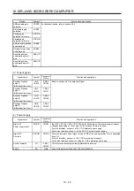
Parameter Description
Setting
range
PC13
Set the lower-order four digits of the standard position of
feedback position
-9999 to 9999 [pulse]
PC14
Set the upper-order four digits of the standard position of
feedback position
-9999 to 9999 [10000 pulses]
(d) Maximum current command (maximum torque) for analog monitor 10 V ±4 V
Values of the maximum current command (maximum torque) when the analog monitor is 10 V ±4 V
are listed.
The current command (torque) outputs the maximum current command (maximum torque) at 10 V
±4 V. The maximum current command (maximum torque) may not match the rated current/maximum
current ratio since it is created from the torque current in the servo amplifier.
Servo motor
Servo amplifier/drive unit
Maximum current command
(maximum torque) [%]
HG-AK series
HG-AK0136
MR-J4W2-0303B6
380
HG-AK0236
MR-J4W2-0303B6
380
HG-AK0336
MR-J4W2-0303B6
363
Содержание MR-J4W2-0303B6
Страница 17: ...8 App 16 Status of general purpose AC servo products for compliance with the China RoHS directive App 58 ...
Страница 39: ...2 INSTALLATION 2 8 MEMO ...
Страница 97: ...4 STARTUP 4 20 MEMO ...
Страница 181: ...6 NORMAL GAIN ADJUSTMENT 6 28 MEMO ...
Страница 235: ...9 DIMENSIONS 9 6 MEMO ...
Страница 245: ...10 CHARACTERISTICS 10 10 MEMO ...
Страница 309: ...13 USING STO FUNCTION 13 14 MEMO ...
Страница 365: ...15 USING A DIRECT DRIVE MOTOR 15 24 MEMO ...
Страница 389: ...16 FULLY CLOSED LOOP SYSTEM 16 24 MEMO ...
Страница 461: ...17 APPLICATION OF FUNCTIONS 17 72 MEMO ...
Страница 556: ...APPENDIX App 41 ...
Страница 585: ...MEMO ...

