13. USING STO FUNCTION
13 - 12
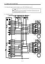
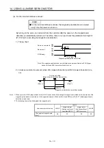
(b) When outputting two STO states by using one TOFB
(Note)
24 V DC ± 10%
MR-J4W2-_B: 350 mA
MR-J4W3-_B: 450 mA
If polarity of diode is
reversed, servo amplifier
will malfunction.
TOFCOM
Servo amplifier
TOFB2
Load
TOFB1
Note. If the voltage drop (maximum of 5.2 V) interferes with the relay operation, apply high
voltage (maximum of 26.4 V) from external source.
13.4.2 Source I/O interface
In this servo amplifier, source type I/O interfaces can be used.
(1) Digital input interface DI-1
This is an input circuit whose photocoupler anode side is the input terminal. Transmit signals from
source (open-collector) type transistor output, relay switch, etc.
24 V DC ± 10%
MR-J4W2-_B: 350 mA
MR-J4W3-_B: 450 mA
Approx. 3.0 k
Ω
V
CES
≤
1.0 V
I
CEO
≤
100 µA
STO1
STO2
Servo amplifier
Switch
Approx. 5 mA
STOCOM
Содержание MR-J4W2-0303B6
Страница 17: ...8 App 16 Status of general purpose AC servo products for compliance with the China RoHS directive App 58 ...
Страница 39: ...2 INSTALLATION 2 8 MEMO ...
Страница 97: ...4 STARTUP 4 20 MEMO ...
Страница 181: ...6 NORMAL GAIN ADJUSTMENT 6 28 MEMO ...
Страница 235: ...9 DIMENSIONS 9 6 MEMO ...
Страница 245: ...10 CHARACTERISTICS 10 10 MEMO ...
Страница 309: ...13 USING STO FUNCTION 13 14 MEMO ...
Страница 365: ...15 USING A DIRECT DRIVE MOTOR 15 24 MEMO ...
Страница 389: ...16 FULLY CLOSED LOOP SYSTEM 16 24 MEMO ...
Страница 461: ...17 APPLICATION OF FUNCTIONS 17 72 MEMO ...
Страница 556: ...APPENDIX App 41 ...
Страница 585: ...MEMO ...

