


Po
sit
io
n
in
g
Chapter 7 Program
7-5
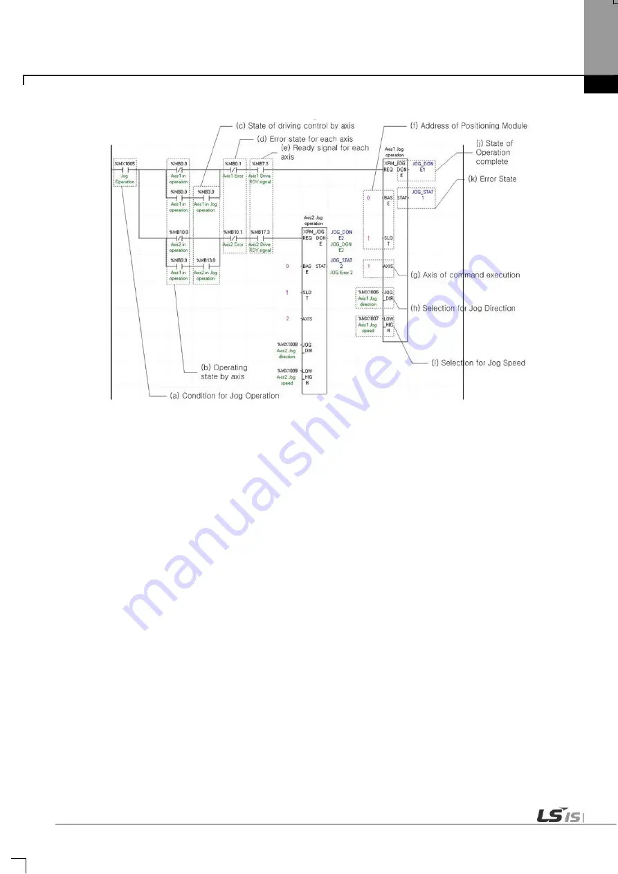
(2) Jog Operation
(a) This is the condition for Jog Operation
This is the condition for Jog Operation Command
(b) Operating state by axis
Jog Operation can only be working when the state of axis set as Jog Operation. In this example above, specific axis
set as Jog Operation otherwise it is not operating.
(c) State of driving control by axis
According to exercise from “Chapter 7.1.2 Current State Reading,” it is a signal of “Jog Operating” for each axis. It
turns on when it is operating. Jog Operation configuration can be changed while it is operating.
(d) Error state for each axis
According to exercise from “Chapter 7.1.2 Current State Reading,” it is a signal of “Error state” for each axis. It turns
on when an error occurred. Operation will only work when there is no error. If you want to operate a system
regardless of errors, you can just inactivate the function.
(e) Ready signal for each axis
According to exercise from “Chapter 7.1.2 Current State Reading,” it is a signal of “Drive Ready” for each axis. This
command only works when this is the condition for Jog Operation is on. If it is not set as “ON,” the “error 413” would
be appeared.
(f) Address of Positioning Module
In this example, Positioning Module is fixed at the 1 slot of 0 bases.
(g) Axis of command execution
Set an axis to execute Jog Operation. UP type can control max. 4 axes. It is available to set 1 ~ 4(axis1~axis4) on
“Axis of command execution” of Jog operation command.
(h) Selection for Jog Direction
Set the direction of Jog operation. If Input value is 0, it will execute Jog operation in forward direction. If Input value is
1, it will execute Jog operation in reverse direction. Direction is can be changed in operation.
(i) Selection for Jog Speed
Содержание XBE-DC08A
Страница 124: ...Main Chapter 1 Configuration and Operation Mode of Programs 1 27 1 Memory block diagram ...
Страница 155: ...Main Chapter 2 CPU Function 2 29 Notice For more details on the monitor refer to the XG5000 manual ...
Страница 504: ...Position Chap 6 Commands 6 61 6 11 Function blocks related to Servo Drive ...
Страница 512: ...Positioning Chapter 7 Program 7 8 manual operation 7 1 4 Parameter and Operation Data Setting 1 Parameter Setting ...
Страница 644: ...Positioning Chapter 8 Functions 8 91 ...
Страница 727: ...Positioning Chapter 9 Positioning Error Information Solutions 9 13 ...
Страница 861: ...Special Chapter 1 Embedded Analog 1 39 5 Select View Variables Comments Variables and comments are both displayed ...
Страница 1206: ...Appendix 2 Dimension App2 1 Appendix 2 Dimension Unit mm 1 CPU Type XEC DN32U 2 Positioning Type XEC DN32UP ...
Страница 1207: ...Appendix 2 Dimension App2 2 2 Analog Type XEC DN32UA ...
Страница 1209: ...Appendix 2 Dimension App2 4 XBE DC08A XBE DC16A XBE TN08A XBE TN16A XBE DR16A XBE RY08A ...
Страница 1210: ...Appendix 2 Dimension App2 5 4 Extension Cnet I F Module XBL C41A XBL C21A ...