


Chapter 2 Built-in Cnet communication
2-86
B
u
ilt
-in
C
omm
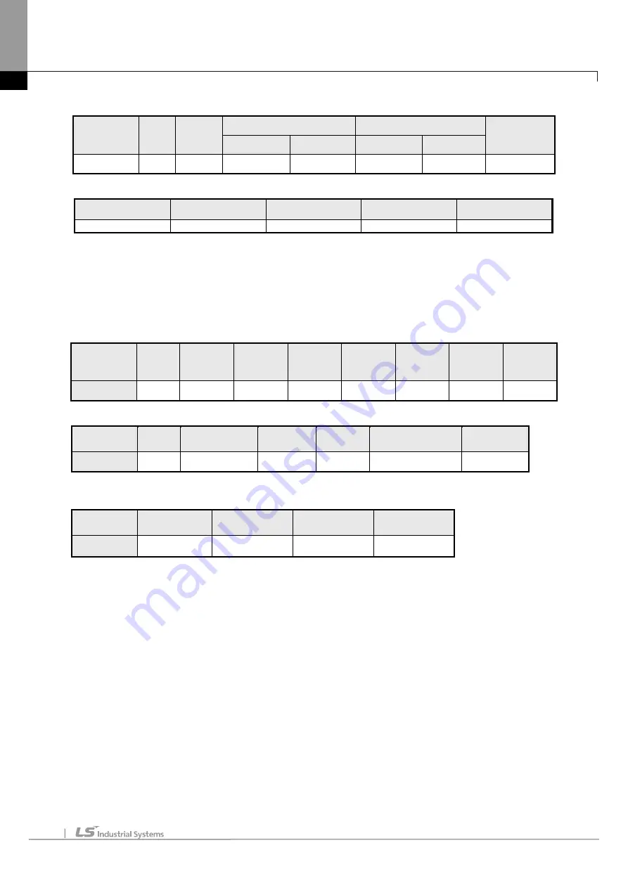
(b) Response frame (In case receiving normal frame)
Classificatio
n
Statio
n no.
Function
code
Address
Output
Error check
Upper byte
Lower byte
Upper byte
Lower byte
Frame
01
06
00
08
00
03
CRC
(c) Response frame (In case of receiving abnormal frame)
Classification
Station no.
Function code
Exceptional code
Error check
Frame
01
86
02
CRC
10) Continuous writing data of bit type at the bit output (0F)
(1) Continuous writing bit of output area
In case of writing continuous bit to output area, request and response frame is as follows.
Tail of frame is applied in case of ASCII mode.
(a) Request frame
Classification
Station
no.
Function
code (0F)
Address
No. of
output
Data size
Output
Frame
error
check
Tail
(CRLF)
Size (byte)
1
1
2
2
1
N
2
2
(b) Response frame (In case of receiving normal frame)
Classification
Station
no.
Function code
(0F)
Address
No. of
output
Frame error check
Tail (CRLF)
Size (byte)
1
1
2
2
2
2
(c) In case of response frame (In case of receiving abnormal frame)
Classification
Station no.
Error code
Exceptional
code
Tail (CRLF)
Size (byte)
1
1
1
2
(2) Details of frame
(a) Station no.: indicates the station no. of slave to write continuous bit of output area.
(b) Function code: ‘06’ indicating Force Multiple Coils
(c) Address: start address of data to read and it consists of 2 byte. At this time, start address conforms to
Modbus address regulation.
(d) No. of output: no. of output to write and it consists of 2 byte
Ex.) When writing 10 continuous data from address number 20, no. of output is 000A(Hex)
(e) Data size: indicates no. of output as byte. Namely, in case data size is 1, no. of data is 9.
Ex.) In case of writing 10 continuous bits, data size is 2.
(f) Output: data value to write in the address set in the Address.
(g) Frame error check: in case of ASCII mode, it uses LRC and in case of STU mode, it uses CRC. It consists of
2 byte.
(h) Tail: it is applies in case of ASCII mode, CRLF is added after LRC.
(i) No. of byte: no. of byte of response data
(j) Error code: error code is expressed by adding 80(Hex) to function code and in case of writing continuous bit
of output area, it is expressed as 8F(Hex).
(k) Exceptional code: indicates detail of error and consists of 1 byte.
Содержание XBE-DC08A
Страница 124: ...Main Chapter 1 Configuration and Operation Mode of Programs 1 27 1 Memory block diagram ...
Страница 155: ...Main Chapter 2 CPU Function 2 29 Notice For more details on the monitor refer to the XG5000 manual ...
Страница 504: ...Position Chap 6 Commands 6 61 6 11 Function blocks related to Servo Drive ...
Страница 512: ...Positioning Chapter 7 Program 7 8 manual operation 7 1 4 Parameter and Operation Data Setting 1 Parameter Setting ...
Страница 644: ...Positioning Chapter 8 Functions 8 91 ...
Страница 727: ...Positioning Chapter 9 Positioning Error Information Solutions 9 13 ...
Страница 861: ...Special Chapter 1 Embedded Analog 1 39 5 Select View Variables Comments Variables and comments are both displayed ...
Страница 1206: ...Appendix 2 Dimension App2 1 Appendix 2 Dimension Unit mm 1 CPU Type XEC DN32U 2 Positioning Type XEC DN32UP ...
Страница 1207: ...Appendix 2 Dimension App2 2 2 Analog Type XEC DN32UA ...
Страница 1209: ...Appendix 2 Dimension App2 4 XBE DC08A XBE DC16A XBE TN08A XBE TN16A XBE DR16A XBE RY08A ...
Страница 1210: ...Appendix 2 Dimension App2 5 4 Extension Cnet I F Module XBL C41A XBL C21A ...