Po
sit
io
n
in
g
Chapter 4 Positioning Parameter & Operation Data
4-32
(7) M Code
(a) M code is applied to the whole axis in a bundle by M code mode set by positioning parameter and is given to each
operation step no. as a Number within the setting range to use at Program.
(b) The setting range is 1
∼
65,535
(c) M code no. can be identified by read by the operation state code
(d) For further information, please refer to M code output of chapter 4.3.2.
(8) Acceleration/Deceleration No
(a) The dual acceleration/deceleration time setting is available by setting the acceleration/deceleration time 1/2/3/ 4 of
basic parameter as acceleration/deceleration no. 1/2/3/4 respectively
.
(9) Operation Speed
(a) Operation speed is the goal speed which it is applied when it operate positioning
(b) Operation speed is set within the range that does not exceed Speed limit of basic parameter.
(10) Dwell Time
(a) This is the waiting time before carrying out the next positioning operation after completing one positioning operation.
(b) Setting range is 0
∼
65,535 (
㎳
).
(c) Especially, in case of using SERVO motor, this is the data to set the waiting time by the stable stop state as positioning
module is in the stop state but actual SERVO motor does not reach to the goal position or in transition state.
(d) While dwell time is active, the corresponding axis of positioning module maintains “ON” of the “Busy Flag” and if dwell
time proceeds, “Busy Flag” becomes “OFF” and the positioning end signal becomes “ON”.
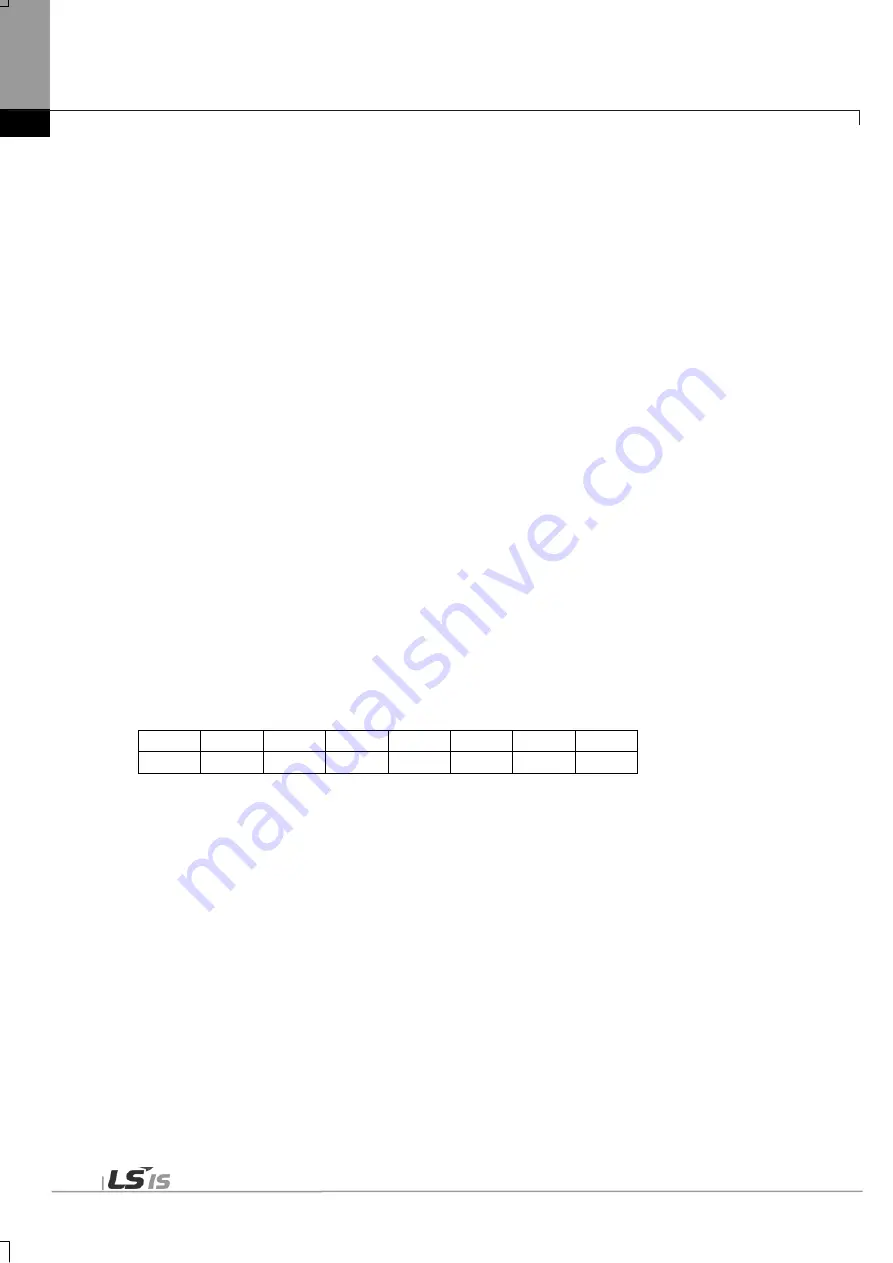
(11) Setting Axis of ordinates
(a) This is an option for axis of ordinates of driving shaft when should operate at least over 2 axis such as linear
interpolation or circular interpolation.
(b) Setting each bit from 1 axis to 4 axis. Each bit is as follows
Bit 7
Bit 6
Bit 5
Bit 4
Bit 3
Bit 2
Bit 1
Bit 0
-
-
-
-
Axis 4
Axis 3
Axis 2
Axis 1
(c) Could choice multiple axes. For example, If choice axis 2 and axis 4 as axis of ordinates, set “000A’by hexadecimal in
setting axis of ordinates
.
(12) Circular interpolating auxiliary position
(a) This is an option for setting auxiliary data when the circular interpolation operates.
(b) According to circular interpolation, mean of circular interpolating auxiliary position is decided.
It means midpoint which is through by circular arc in midpoint method.
It is central point of circular arc in central point method. And It is radius of circular arc in radius method.
(c) In case that circular interpolation method is radius, be valid only value of circular interpolating auxiliary position of
principal axis.
(d) For further information, please refer to “Circular interpolating control” of 8.2.9 ~ 8.2.11.
(13) Circular interpolating method
(a) This is an option for method setting from circular interpolating operation.
(b) There are three method for circular interpolation; midpoint, central point, radius.
(c) For further information, please refer to “Circular interpolation control” of 8.2.9 ~ 8.2.11.
Содержание XBE-DC08A
Страница 124: ...Main Chapter 1 Configuration and Operation Mode of Programs 1 27 1 Memory block diagram ...
Страница 155: ...Main Chapter 2 CPU Function 2 29 Notice For more details on the monitor refer to the XG5000 manual ...
Страница 504: ...Position Chap 6 Commands 6 61 6 11 Function blocks related to Servo Drive ...
Страница 512: ...Positioning Chapter 7 Program 7 8 manual operation 7 1 4 Parameter and Operation Data Setting 1 Parameter Setting ...
Страница 644: ...Positioning Chapter 8 Functions 8 91 ...
Страница 727: ...Positioning Chapter 9 Positioning Error Information Solutions 9 13 ...
Страница 861: ...Special Chapter 1 Embedded Analog 1 39 5 Select View Variables Comments Variables and comments are both displayed ...
Страница 1206: ...Appendix 2 Dimension App2 1 Appendix 2 Dimension Unit mm 1 CPU Type XEC DN32U 2 Positioning Type XEC DN32UP ...
Страница 1207: ...Appendix 2 Dimension App2 2 2 Analog Type XEC DN32UA ...
Страница 1209: ...Appendix 2 Dimension App2 4 XBE DC08A XBE DC16A XBE TN08A XBE TN16A XBE DR16A XBE RY08A ...
Страница 1210: ...Appendix 2 Dimension App2 5 4 Extension Cnet I F Module XBL C41A XBL C21A ...


