GE
D
IRECTION
5573152-100, R
EV
. 2
LOGIQ E9 S
ERVICE
M
ANUAL
Chapter 8 Replacement procedures
8 - 131
4.
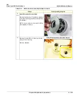
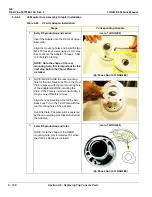
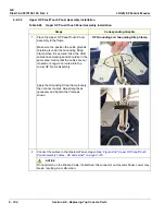
Insert the Adapter into the Frame UI Upper
Assembly with the rear mounting hole at
the rear.
Align the mounting holes and install the two
M5 x 50 hex key screws using a 4 mm Hex
Key to secure the Adapter. Torque 2.5 Nm
(1.8 lbf-ft {21.6 lbf-in}).
NOTE: Note the four bosses on the
Adapter Bearing surface, these capture
and position the Bearing when it is
installed.
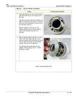
5.
NOTE: MAKE SURE the REAR mounting
hole for the Arm Neck Lock Pin, in the
Bearing is aligned with the REAR mounting
hole and the four bosses of the Adapter
capture and position the Bearing.
The Bearing should seat firmly on the
Adapter. If the Bearing “rocks“, it is NOT
installed correctly.
(space intentionally left blank)
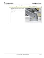
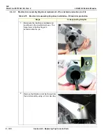
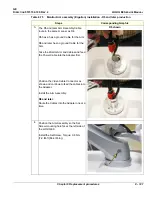
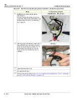
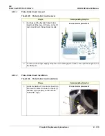
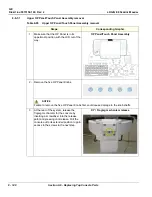
Table 8-80 V2 Arm Adapter installation
Steps
Corresponding Graphic
Содержание LOGIQ E9
Страница 1: ...12 13 18 GEHC_FRNT_CVR FM LOGIQ E9 SERVICE MANUAL VERSION R6 Part Number 5573152 100 Revision Rev 2 ...
Страница 2: ......
Страница 11: ...GE DIRECTION 5573152 100 REV 2 LOGIQ E9 SERVICE MANUAL xi ZH CN KO ...
Страница 140: ...DIRECTION 5573152 100 REV 2 LOGIQ E9 SERVICE MANUAL 4 50 Section 4 8 Site Log This page was intentionally left blank ...
Страница 753: ......
Страница 754: ......


