GE
D
IRECTION
5573152-100, R
EV
. 2
LOGIQ E9 S
ERVICE
M
ANUAL
5 - 6
Section 5-2 - LOGIQ E9 description
5-2-5
Signal flow overview
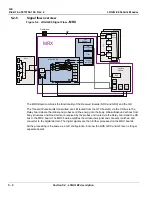
The MRX Board combines the functionality of the Receiver Boards (DRX and GRX) and the GFI.
The Transmit Pulse bursts transmitted, are still routed from the GTX board(s) via the XD bus to the
Relay board where the ultrasound probes send the energy into the body. Weak ultrasound echoes from
body structures and blood cells are received by the probes and routed via the Relay board and the XD
bus to the MRX board. The MRX board amplifies the ultrasound signal and connects it with an A/D
converter to the digital domain. The digital signals are then further processed on the MRX boards.
All the processing is the same as a GFI configuration, but now the DRX, GRX and GFI are no longer
separate boards.
Figure 5-4 LOGIQ E9 Signal Flow
- MRX
GTX 64 Ch
GTX
64 Ch
GTX 64 Ch
256
256
MRX
Frontplane
GRLY
256
R
e
l
a
y
s
192
192
192
GDIF
David
1
David
2
Pulser
David
3
Pulser
...
David
0
T/ R
A
/
D
A/DA
Nathan
32 Ch
TGC
TGC
TGC
TGC
TGC
X
Nathan
32 Ch
Nathan
32 Ch
Nathan
32 Ch
Nathan
32 Ch
Nathan
32 Ch
MRX 192 Ch
X
I
CW
Option
Analog
Beamformer
Filter
A/D
Converters
I / Q
Front End
Interface
GFE
SED
DSP
Test
Gen
TGC
Gen
X
A/DA
A/DA
A/DA
Q
Содержание LOGIQ E9
Страница 1: ...12 13 18 GEHC_FRNT_CVR FM LOGIQ E9 SERVICE MANUAL VERSION R6 Part Number 5573152 100 Revision Rev 2 ...
Страница 2: ......
Страница 11: ...GE DIRECTION 5573152 100 REV 2 LOGIQ E9 SERVICE MANUAL xi ZH CN KO ...
Страница 140: ...DIRECTION 5573152 100 REV 2 LOGIQ E9 SERVICE MANUAL 4 50 Section 4 8 Site Log This page was intentionally left blank ...
Страница 753: ......
Страница 754: ......


